
October 02, 2026

Sintered Porous Metal Spargers help control gas distribution, but anti-clogging spargers are needed when solids, oils, biofilm, or crystallized chemicals block the pores. A clogged sparger creates uneven gas dispersion and reduces mass transfer. Fine bubble aeration can then lose efficiency because fewer active pores release gas. In fermentation, poor oxygen transfer may slow cell growth and reduce product yield. In wastewater treatment, dead zones can form when an air diffuser cannot deliver a stable bubble pattern.
Many operators first notice a higher gas pressure, unstable flow, or a drop in dissolved oxygen. These symptoms can also appear in gas sparging systems used for hydrogenation, ozone injection, nitrogen stripping, and chemical reactors. The correct pore size, metal grade, surface finish, and cleaning method can prevent repeated failure.
Anti-clogging spargers are needed when a process contains suspended solids, viscous liquids, biological growth, oil, salts, or particles that can block small gas outlets. They are used to maintain stable gas flow, reduce pressure rise, improve bubble distribution, and extend cleaning intervals. Sintered porous metal spargers are a strong choice because their pore structure is uniform, their bodies tolerate repeated cleaning, and their pore size can be selected for the gas and liquid conditions.
An anti-clogging sparger is a gas distribution device designed to resist pore blockage during continuous operation. It may use a sintered stainless steel element, a larger pore size, a hydrophobic surface, a protective screen, or a back-purge design.
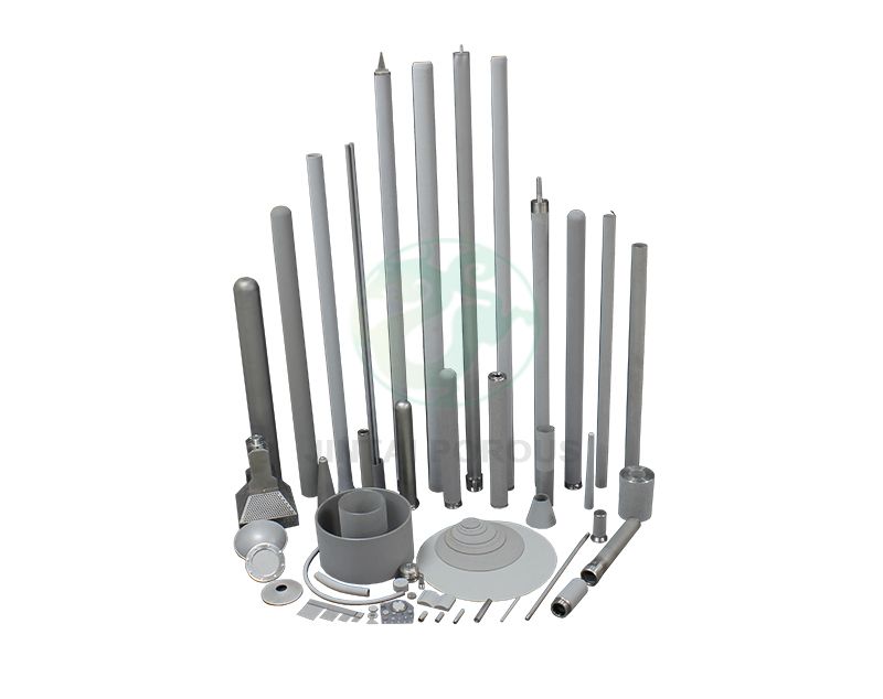
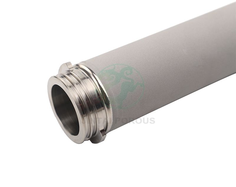
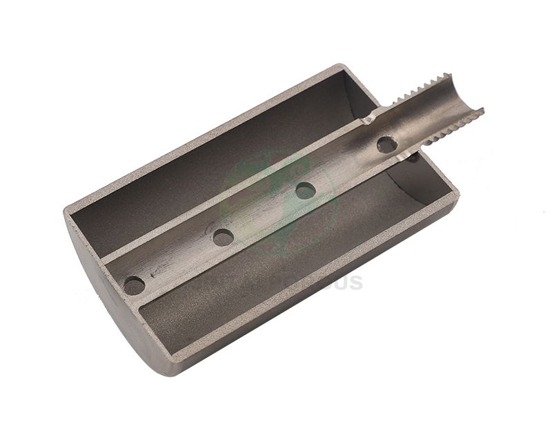
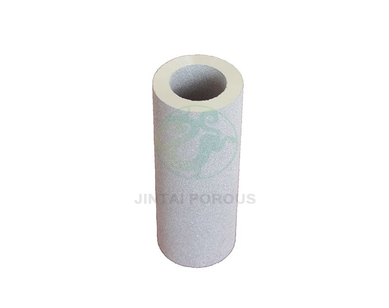
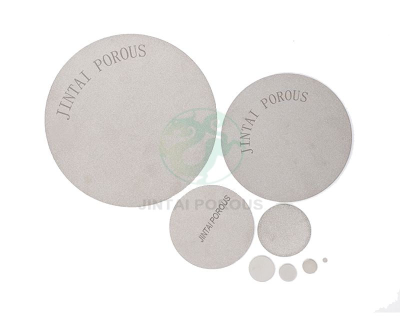
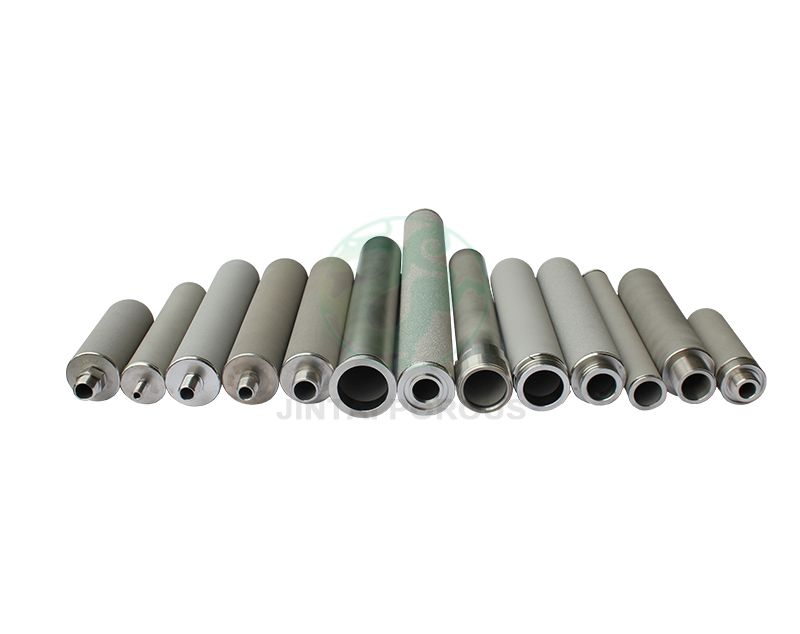
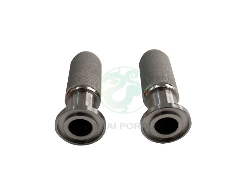
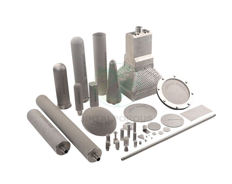
A sintered porous metal sparger is made by compacting metal powder and heating it below the metal's melting point. The process joins the particles and creates connected pores. The final element can be manufactured as a tube, plate, disk, candle, or custom assembly.
Smaller pores can produce smaller bubbles and higher gas-liquid contact area. However, they also create more resistance to flow and can block faster when the liquid contains solids. Larger pores are easier to clean and provide lower pressure drop, but they may produce larger bubbles.
| Design factor | Typical engineering range | Effect on operation |
|---|---|---|
| Nominal pore size | 0.5 to 100 micrometers | Controls bubble size, gas resistance, and particle tolerance |
| Open porosity | 30 to 45 percent | Influences gas capacity and pressure drop |
| Material | 316L stainless steel, 304 stainless steel, nickel, or titanium | Determines chemical and temperature resistance |
| Operating temperature | Application dependent; many stainless steel systems operate above 200 degrees Celsius | Must match the metal grade, seal, and process fluid |
| Connection | NPT, tri-clamp, flange, weld, or custom fitting | Controls installation time and leak risk |
Particles larger than the effective pore opening can lodge at the surface. Smaller particles can enter the porous structure and build an internal cake. This problem is common in mineral processing, chemical precipitation, wastewater treatment, and slurry mixing.
For a liquid with particles up to 50 micrometers, a sparger with a 1 micrometer pore rating may clog quickly unless the liquid is filtered or the sparger includes a cleaning cycle. In many cases, a 10 to 40 micrometer pore design provides a better balance between gas dispersion and operating life.
Fermentation broth and wastewater can contain proteins, cells, organic matter, and bacteria. These materials may form a biofilm on the gas outlet. The biofilm increases pressure drop and reduces the active area of the sparger.
Regular cleaning in place can reduce this risk. Steam, hot water, chemical cleaning, or back-pulsing may be selected based on the process material and metal grade.
Oil and condensed vapor can spread across the pore surface. This can prevent gas from entering the liquid and can create a sudden increase in pressure. Upstream coalescing filters, drain points, and heated gas lines can reduce this type of fouling.
| Observed symptom | Possible cause | Recommended check |
|---|---|---|
| Gas pressure increases by more than 20 percent | Pore blockage, wetting, or a blocked gas line | Compare pressure with the original clean baseline |
| Bubble coverage becomes uneven | Partial clogging or damaged distribution area | Inspect bubble pattern at the design gas rate |
| Gas flow decreases while control valve position remains unchanged | Higher resistance through the sparger | Check flow meter, regulator, and sparger pressure drop |
| Dissolved oxygen falls | Lower gas transfer or poor mixing | Measure dissolved oxygen at several tank locations |
| Large bubbles appear from only a few areas | Partial wetting, cracks, or local pore damage | Perform a visual inspection and integrity test |
Random holes can create uneven gas release. Sintered metal creates many connected passages through the element. When the powder size, compaction pressure, and sintering temperature are controlled, the manufacturer can produce a repeatable pore structure.
316L stainless steel is often selected for food, pharmaceutical, chemical, and water treatment systems. It provides good corrosion resistance in many environments. Titanium may be considered for chloride-rich or highly corrosive service. The correct choice must be based on the liquid chemistry, temperature, pressure, and cleaning agents.
A metal sparger can often be cleaned without replacing the entire assembly. The cleaning method should be validated with pressure drop and flow testing. A sparger that returns to within 10 percent of its original clean pressure drop after cleaning is generally easier to manage than one that shows permanent resistance growth.
| Design option | Best use | Main benefit | Important limitation |
|---|---|---|---|
| Coarser pore size | Slurries and liquids with suspended solids | Lower blockage risk and lower pressure drop | May produce larger bubbles |
| Back-purge connection | Continuous production systems | Removes surface deposits without full removal | Needs a clean gas source and control valve |
| Protective pre-filter | Gas streams with dust or oil | Reduces contamination before it reaches the pores | Creates an additional maintenance point |
| Hydrophobic treatment | Moist gas and condensate-prone lines | Reduces liquid wetting of the gas passage | Must be compatible with the process and cleaning cycle |
| Multiple sparger zones | Large tanks and reactors | Maintains distribution if one zone needs service | Requires more valves and controls |
| Flush ports | Viscous liquids and crystallizing solutions | Supports liquid cleaning and drain-down | Needs correct piping design |
The sparger must operate within the available gas pressure. A practical design should include the pressure loss in the gas line, valve, connector, and sparger. For example, if a blower supplies 150 kilopascals of gauge pressure and the piping consumes 40 kilopascals, the sparger and control system have about 110 kilopascals available before other safety allowances.
Testing should measure pressure drop at three flow points. A useful test plan may include 25 percent, 50 percent, and 100 percent of the design gas flow. The results show whether the sparger remains stable across the operating range.
Viscosity affects bubble release and gas distribution. A liquid with a viscosity of 50 millipascal seconds behaves differently from water at about 1 millipascal second. Slurries also require information about particle size distribution, solids concentration, and settling behavior.
Fine bubbles offer a high gas-liquid contact area. They are often used for oxygen transfer, ozone treatment, and carbon dioxide absorption. Coarser bubbles can be better for mixing heavy slurries or reducing clogging risk. The best design is not always the smallest pore size.
Step 1: Collect gas and liquid data
Step 2: Identify the main fouling mechanism
Step 3: Select material, pore size, and open area
Step 4: Test pressure drop and bubble distribution
Step 5: Run a pilot installation
Step 6: Set cleaning and inspection limits
Step 7: Review operating data and adjust the design
Record the gas, liquid, temperature, pressure, flow rate, viscosity, pH, solids content, and cleaning chemicals. Also record the available space and connection type.
Determine whether the main problem is particulate blockage, salt deposition, biological fouling, oil wetting, or mechanical damage. One process may have more than one fouling mechanism.
Choose the pore size based on the required bubble pattern and the largest expected contaminant. If the liquid contains large particles, add upstream filtration or select a larger pore size. If fine bubbles are required, plan for more frequent cleaning or use several replaceable zones.
Measure clean pressure drop, gas flow, bubble distribution, leakage, and mechanical strength. Bubble point testing can help identify changes in pore structure. ASTM F316 is commonly used for bubble point and pore size testing of membrane-like porous materials, while powder and sintered metal production may also use powder metallurgy inspection methods such as ASTM B243 terminology and related procedures.
A pilot test should run for a defined period. A 72-hour test may reveal early wetting or installation problems. A 30-day test is more useful for biological or mineral fouling. Record pressure drop at least once per shift or once per day, depending on process risk.
For example, an operator may schedule cleaning when pressure drop rises 15 to 25 percent above the clean baseline. The exact limit depends on the blower capacity, process safety, and product requirements.
| Inspection item | Typical method | Example acceptance target |
|---|---|---|
| Dimensions | Caliper, micrometer, coordinate measurement, or gauge | Within the approved drawing tolerance |
| Pore size | Bubble point, permeability, or laboratory pore analysis | Within the specified nominal range |
| Gas permeability | Controlled air or nitrogen flow test | Within the approved flow band at a defined pressure |
| Pressure drop | Flow bench test | Below the project maximum at full design flow |
| Leak integrity | Pressure decay, bubble test, or helium leak test | No leak above the project limit |
| Surface condition | Visual inspection and magnified inspection | No cracks, dents, loose particles, or blocked connection |
| Material verification | Material certificate and positive material identification | Grade matches the approved specification |
JINTAI can use a documented inspection plan that links each sparger to a material certificate, dimensional report, permeability result, and pressure test record. For repeat orders, statistical process control can track key values such as pore size, gas permeability, and pressure drop. A sample plan may inspect 100 percent of critical dimensions and test 100 percent of finished assemblies for leakage.
Cleaning is not complete when the surface looks clean. Measure the pressure drop and gas flow after cleaning. Compare the result with the original baseline. If flow recovery is less than 90 percent, inspect the element for internal blockage, chemical damage, or permanent deformation.
Never use a cleaning chemical without checking compatibility with the metal, welds, seals, and process. Chloride exposure can create corrosion risks in stainless steel under certain temperature and concentration conditions.
The following example shows how an anti-clogging design can be evaluated. It is an engineering example, not a guarantee of performance.
A slurry tank used a 2 micrometer porous element at a gas flow of 20 normal cubic meters per hour. The liquid contained 2 percent suspended solids and had a viscosity of 12 millipascal seconds. After 10 days, pressure drop increased from 35 kilopascals to 58 kilopascals.
The redesign used a 15 micrometer sintered stainless steel sparger, a gas pre-filter, and a weekly back-purge. The pilot test lasted 30 days. Pressure drop reached 42 kilopascals, and the bubble pattern remained stable. The larger pore size reduced fine bubble performance, but gas coverage improved because more of the sparger surface remained active.
| Measure | Original design | Anti-clogging design |
|---|---|---|
| Pore size | 2 micrometers | 15 micrometers |
| Gas flow | 20 normal cubic meters per hour | 20 normal cubic meters per hour |
| Initial pressure drop | 35 kilopascals | 33 kilopascals |
| Pressure drop after test | 58 kilopascals after 10 days | 42 kilopascals after 30 days |
| Cleaning support | Manual removal | Gas pre-filter and weekly back-purge |
A smaller pore may reduce initial bubble size, but it also increases resistance. If the liquid has solids or biological material, the surface can block before the expected gas transfer benefit is achieved. A stable gas pattern over 30 days may be more valuable than a fine bubble pattern that lasts only 3 days.
| Diffuser type | Clogging resistance | Cleaning ability | Typical application |
|---|---|---|---|
| Sintered porous metal sparger | Medium to high when correctly specified | Good with back-purge, flushing, or chemical cleaning | Reactors, fermentation, wastewater, gas-liquid contact |
| Flexible membrane diffuser | Medium | Usually limited by membrane material | Aeration tanks and water treatment |
| Drilled pipe sparger | High against fine pore blockage | Easy to flush | Coarse bubble mixing and heavy slurries |
| Ceramic diffuser | Low to medium depending on liquid | Can be brittle during handling | Fine bubble aeration and laboratory systems |
| Perforated plate | High for large particles | Easy to clean | Low-resistance gas distribution |
JINTAI can support the design of sintered porous metal spargers for gas dispersion, fine bubble aeration, fermentation, wastewater treatment, chemical processing, and laboratory equipment. The project specification can include metal grade, pore size, porosity, dimensions, gas flow, pressure drop, connection type, cleaning method, and inspection records.
A practical development program may include 3 to 5 design samples, testing at 25 percent, 50 percent, and 100 percent gas flow, and a pilot run of at least 72 hours. For fouling-sensitive processes, a 30-day evaluation with daily pressure records gives more useful data than a short visual test.
Before production approval, request a drawing, material certificate, pore or permeability data, pressure test result, leak test result, and cleaning recommendation. These records make it easier to compare batches and identify performance changes.
Anti-clogging spargers are needed when solids, oil, biological material, crystals, or viscous liquids threaten stable gas distribution. The best solution is not simply to choose the smallest pore size. Engineers must balance bubble size, pressure drop, gas flow, liquid properties, material compatibility, cleaning access, and inspection data.
A properly designed sintered porous metal sparger can provide uniform gas dispersion, strong mechanical performance, and repeatable cleaning results. With the right pore size, pre-filtration, back-purge plan, and quality inspection, anti-clogging spargers can reduce pressure rise and protect process performance.