
October 05, 2026

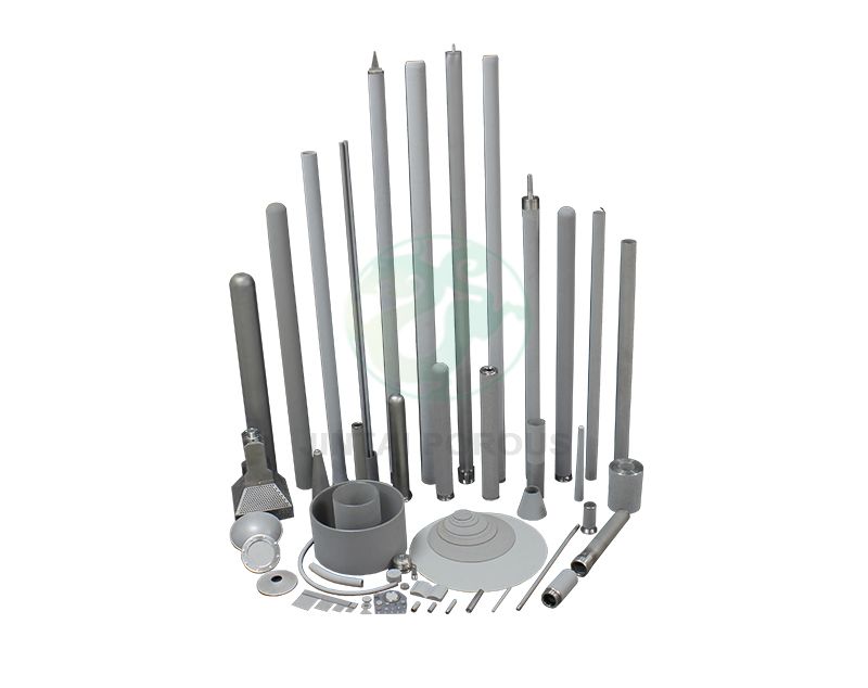
Sintered porous asymmetric filter elements help chemical plants remove fine solids while controlling pressure drop and maintenance cost. Chemical processing often involves corrosive liquids, high temperatures, suspended catalysts, and changing particle loads. Porous metal media can provide surface filtration with a strong support structure. A stainless steel sintered filter element for corrosive chemicals can also support repeated cleaning and reuse. The main design factors are pore size distribution, chemical compatibility, and operating pressure. This article explains how asymmetric metal filter elements work, how to select them, and how JINTAI applies testing data to chemical process filtration.
Asymmetric metal filter elements use layers with different pore sizes to improve particle capture, flow stability, and service life. The coarse outer layer supports the element and reduces blockage. The fine inner layer controls the filtration rating. This design is useful for chemical liquids, gases, catalyst recovery, solvent recovery, and high-temperature process filtration. A suitable element should match the required micron rating, flow rate, pressure differential, temperature, cleaning method, and chemical compatibility. Sintered stainless steel, nickel alloy, and other metal grades can be selected for the process conditions.
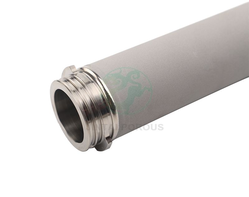
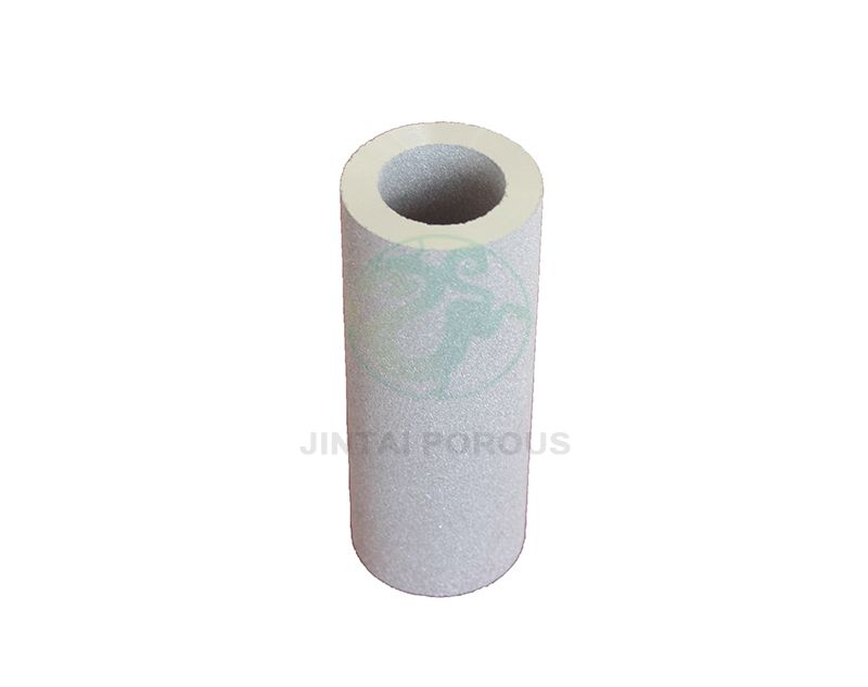
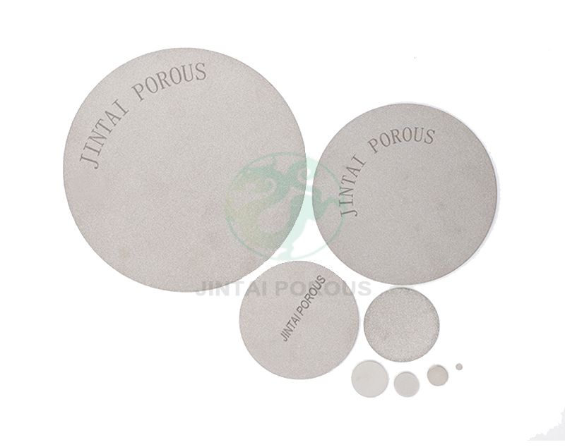
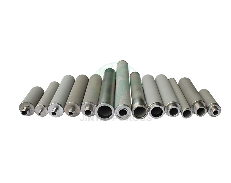
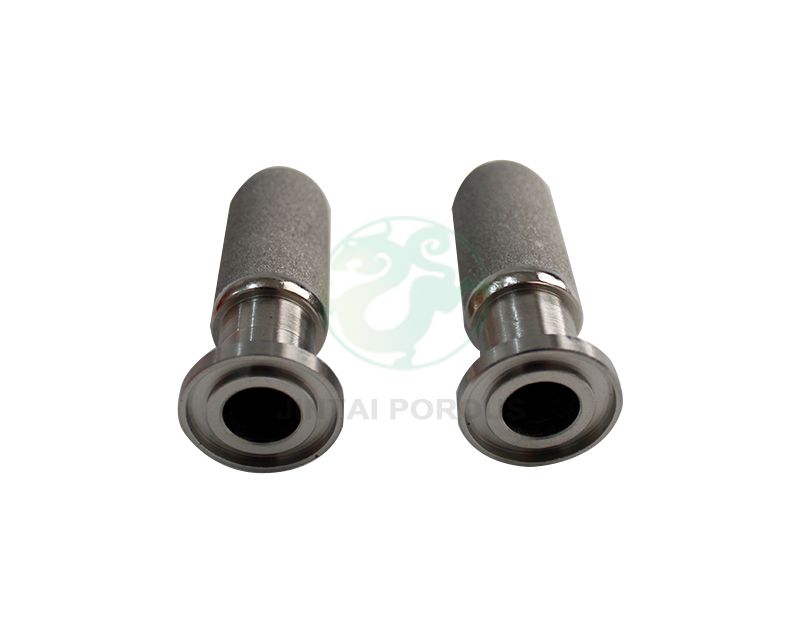
An asymmetric metal filter element is a porous component made from sintered metal powder, wire mesh, or a combination of both. Its pore structure is not the same through the full wall thickness. One side has larger pores. Another side has smaller pores. This creates a graded filtration path.
During sintering, metal particles are heated below their melting point. The particles bond at their contact points. The result is a rigid body with connected pores. The pore network allows fluid to pass while retaining solid particles.
This structure combines surface filtration and depth filtration. Larger particles are held near the upstream surface. Smaller particles are captured within the fine layer. This can delay blockage when the feed contains a wide range of particle sizes.
| Parameter | Typical design range | Why it matters |
|---|---|---|
| Nominal filtration rating | 0.5 to 100 microns | Controls the target particle size for removal. |
| Porosity | 30 to 45 percent | Affects flow rate, pressure drop, and dirt-holding capacity. |
| Operating temperature | -20 to 500 degrees C for many stainless steel designs | Depends on alloy, seals, pressure, and chemical exposure. |
| Clean differential pressure | Commonly 0.01 to 0.10 MPa at the rated flow | Shows the resistance of a clean element. |
| Recommended replacement pressure | Often 0.10 to 0.30 MPa above the clean baseline | Must be confirmed by the equipment and process owner. |
| Material options | 316L stainless steel, 304 stainless steel, nickel alloys, titanium | Determines corrosion resistance and temperature capability. |
These ranges are general engineering values. The final specification should be based on fluid properties, test results, and the filter housing design.
Chemical streams may contain catalyst fines, crystallized salts, carbon particles, metal oxides, or polymer gels. A single uniform pore layer can block quickly when the feed contains mixed particle sizes. An asymmetric structure distributes the solids through more than one layer.
For example, a 5 micron fine layer can be supported by 20 to 40 micron layers. The larger pores help reduce the initial pressure drop. The fine layer provides the final retention function.
Metal filters do not soften in the same way as many polymer filter media. A sintered metal element can be used in hot gas filtration, polymer production, solvent treatment, and other applications where temperature exceeds the limits of common polypropylene or nylon media.
Temperature resistance is not determined by the filter material alone. Seals, welds, housing connections, and thermal cycling must also be checked. A filter rated for 500 degrees C in a laboratory may need a lower operating limit in a complete assembly.
Common cleaning methods include reverse-flow backwashing, clean gas pulsing, ultrasonic cleaning, solvent flushing, and controlled chemical cleaning. The method depends on the retained material and the filter alloy.
A reusable metal filter element for solvent recovery may be cleaned many times if it is operated below its mechanical limits. After cleaning, the element should be inspected for cracks, deformation, blocked pores, and changes in pressure drop.
Asymmetric metal filters are used to remove suspended solids from acids, alkalis, solvents, oils, resins, and process water. The correct alloy and weld design are important when the fluid contains chloride, sulfur compounds, strong acids, or strong bases.
For a high viscosity liquid, the filter area must be large enough to keep the pressure drop within the pump limit. A filter that works for water may not work for a resin or polymer solution at the same flow rate.
Porous metal media can remove dust, catalyst particles, and condensable solids from hot gases. High temperature gas filtration with porous metal media requires attention to gas velocity, thermal expansion, pulse cleaning, and particle adhesion.
Catalyst particles can have high value. A fine metal filter can separate catalyst solids from a liquid or gas stream. The filter rating should be selected from particle size data, not only from the average particle diameter.
Solvent recovery systems often need low contamination, stable flow, and chemical-resistant materials. A stainless steel sintered filter element for corrosive chemicals may be suitable for some solvent systems, while nickel alloy or titanium may be needed for more aggressive fluids.
Pressure drop increases as the element collects solids. It also increases when fluid viscosity rises or when the flow rate is too high. The design should begin with the clean pressure drop and include enough area for the expected dirt load.
A basic sizing relationship is:
Required filter area = Process flow rate divided by allowable flow per unit area
The allowable flow per unit area must come from pilot testing or supplier data. It is not a universal value. For high viscosity liquids, lower flux is normally required.
Nominal and absolute ratings are not identical. A nominal rating may describe general particle removal. An absolute rating is linked to a defined test condition and retention level.
Ask for the test method, test dust or contaminant, fluid viscosity, flow rate, and pass or fail limit. A 1 micron rating from one supplier may not perform the same as a 1 micron rating from another supplier.
| Material | Common advantages | Selection notes |
|---|---|---|
| 316L stainless steel | Good general corrosion resistance and weldability | Check chloride level, temperature, and acid concentration. |
| 304 stainless steel | Cost-effective for mild chemical service | Not suitable for every chloride or acidic environment. |
| Nickel alloys | Useful for severe corrosion and high temperature | Higher material cost and more demanding fabrication. |
| Titanium | Strong resistance in selected chloride and oxidizing conditions | Compatibility must be checked for reducing acids and mixed chemicals. |
Chemical compatibility should be reviewed at the real concentration, temperature, pressure, and exposure time. A general material chart is only a starting point.
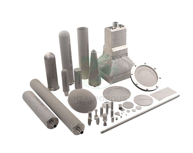
The manufacturing route affects pore size, strength, permeability, and service life. JINTAI can use powder metallurgy, multilayer sintering, welding, and precision machining to produce filter elements for different chemical process systems.
Step 1: Define the specification
Record the micron rating, flow rate, temperature, pressure, alloy, dimensions, connection type, and cleaning method.
Step 2: Prepare the metal layers
Select coarse support powder, intermediate powder, and fine filter powder. Control particle size and material purity.
Step 3: Form the asymmetric blank
Stack, press, roll, or otherwise form the layers in the required order. Avoid layer separation during handling.
Step 4: Sinter the structure
Heat the blank in a controlled atmosphere. The sintering cycle bonds the particles without closing the connected pores.
Step 5: Machine and weld
Machine the element to the specified diameter and length. Weld end caps, supports, and connections with controlled heat input.
Step 6: Clean and inspect
Remove loose particles, oils, and processing residue. Complete dimensional, visual, permeability, and integrity checks.
Step 7: Test and release
Compare the results with the approved specification. Record the material batch, production lot, test data, and final inspection status.
Inspectors measure length, outside diameter, inside diameter, wall thickness, connection dimensions, and flatness. A common production plan checks 100 percent of critical dimensions for small batches. Larger batches may use a documented sampling plan based on customer requirements.
The surface should be free from visible cracks, dents, open weld defects, and loose contamination. Welds may be checked by dye penetrant testing when the design and alloy permit this method.
Air or liquid permeability testing measures the flow through the clean element at a defined pressure. The test report should include:
A sudden change from the approved permeability range may indicate blocked pores, an incomplete weld, or a forming problem.
Bubble point testing can help identify the largest connected opening in a wetted porous structure. The result depends on the test liquid, surface tension, wetting quality, and test procedure.
ISO 2942 is commonly referenced for filter element fabrication integrity and verification concepts. ASTM F316 is widely used for bubble point and pore size testing of membrane filters. The chosen method must be suitable for the metal element and agreed before production.
Particle challenge testing can measure removal performance under controlled conditions. ISO 16889 is associated with multipass testing for hydraulic filter elements. It should not be applied to every chemical filter without checking scope and test design.
For chemical process filtration, the most useful test may use the actual process fluid and representative solids. The test should report particle concentration before and after the element, flow rate, pressure drop, and test duration.
A reuse study may include 10, 20, or more cleaning cycles. After each cycle, measure pressure drop, permeability, dimensions, and integrity. A practical acceptance rule is that the post-cleaning permeability remains within the approved range and the element passes the integrity test.
| Filter media | Strength | Limitation | Suitable use |
|---|---|---|---|
| Asymmetric sintered metal | High strength, graded pores, reusable design | Higher purchase cost than disposable media | Chemical process filtration, catalyst recovery, hot gas filtration |
| Uniform sintered metal | Simple structure and predictable production | May block faster with mixed particle sizes | Stable feed streams with controlled solids |
| Wire mesh | Good surface filtration and easy cleaning | Limited depth capture and limited fine rating | Coarse particle removal and support layers |
| Polymer membrane | Fine filtration and low initial cost | Lower heat resistance and possible solvent limitations | Moderate temperature liquid filtration |
| Bag filter | Large dirt capacity and simple replacement | Usually disposable and less suitable for high heat | Bulk liquid solids removal |
Common signs include a rising pressure drop, lower downstream flow, unstable product quality, or reduced gas permeability. Cleaning should start before the element reaches a condition that causes permanent pore blockage.
Replace the element if it has a crack, damaged weld, permanent deformation, failed integrity test, or a pressure drop that does not return to the approved clean range after cleaning.
JINTAI can use these operating details to define the filter layer structure, material, dimensions, connection design, and inspection plan. A pilot test is recommended when the feed contains high solids, high viscosity, or difficult-to-characterize particles.
Asymmetric metal filter elements for chemical process filtration use graded pore layers to balance particle retention, flow, strength, and cleanability. They are suitable for liquid chemical filtration, catalyst recovery, solvent recovery, and high temperature gas filtration with porous metal media. Correct selection requires data on particle size, flow rate, viscosity, pressure, temperature, chemical compatibility, and cleaning conditions. With controlled sintering, documented testing, and regular maintenance, a Sintered Porous Asymmetric Filter Element can provide reliable and reusable filtration for demanding chemical processes.