
Quick answer: Gas flow rate controls bubble size, release frequency, and pressure demand in a porous metal sparger. A lower gas flow rate usually creates smaller bubbles, while a higher rate can cause bubble growth, coalescence, and unstable gas release.

Gas flow rate is the first value engineers check when selecting a sparger. Bubble size depends on pore size, liquid properties, pressure drop, and gas-liquid mass transfer. A sintered porous metal sparger can produce a wide range of bubbles by changing its pore structure and operating conditions. This guide explains the relationship in simple terms.
For many water-like liquids, a starting gas loading of 0.05 to 0.30 Nm3/h/cm2 of active sparging area may produce bubbles in the 0.5 to 3 mm range. This is a design starting point, not a fixed rule. Actual results depend on the metal grade, pore size, liquid depth, viscosity, surface tension, and gas pressure.

Gas flow rate is the amount of gas entering the sparger during a specific period. It is commonly shown as Nm3/h, L/min, or m3/h. The letter N means the gas volume is corrected to a standard temperature and pressure.
When comparing spargers of different sizes, engineers often use gas flux. Gas flux is the gas flow rate divided by the active sparger area. This value gives a more useful comparison than total flow alone.
Gas flux formula: Gas flux = gas flow rate / active sparging area
Example: A flow of 60 L/min through 200 cm2 of active area equals 0.30 L/min/cm2.

A 100 L/min flow may be low for a large tube but very high for a small disc. If the area is too small, the gas may form large bubbles, channels, or a continuous gas layer. Therefore, use gas flux when scaling a process from laboratory equipment to production equipment.
1. What Gas Flow Rate Means in a Porous Metal Sparger
A porous metal sparger contains many connected pores. Gas pressure pushes gas through these pores and into the liquid. At the pore outlet, surface tension holds the gas until the bubble becomes large enough to detach.
At a low flow rate, each pore releases gas slowly. The bubble has more time to detach before it grows too large. At a high flow rate, gas enters the pore faster. The bubble can grow before detachment and may join with nearby bubbles.
| Gas flow condition | Typical bubble behavior | Common process result |
|---|---|---|
| Low gas flux | Small and separated bubbles | Good gas dispersion and stable operation |
| Medium gas flux | Regular bubbles with higher release frequency | Good mixing and useful mass transfer |
| High gas flux | Larger bubbles and bubble coalescence | More channeling, noise, and gas loss |
| Excessive gas flux | Continuous gas pockets or jetting | Unstable pressure and poor contact efficiency |
Why total flow can be misleading
Small bubbles provide a larger gas-liquid contact area. This can improve oxygen transfer, carbon dioxide removal, hydrogen distribution, and ozone dissolution. However, very small bubbles may increase pressure demand and create more liquid foaming.
The best bubble size depends on the process. A fermentation tank may need fine and even oxygen dispersion. A wastewater aeration tank may require high oxygen transfer at a reasonable energy cost. A chemical reactor may need controlled gas distribution instead of the smallest possible bubbles.
2. How Gas Flow Rate Changes Bubble Formation
Small bubbles are not always the best choice
Pore size is one of the most important sparger design factors. A smaller pore usually creates a smaller initial bubble. However, a small pore also increases pressure drop and may block more easily if the gas or liquid contains particles.
Pore distribution is also important. A sparger with a narrow pore range can provide more even gas release. A wide pore range may cause gas to favor the largest and easiest flow paths.
3. The Main Factors That Control Bubble Size
The gas must overcome liquid head, sparger resistance, piping losses, and surface tension at the pore opening. If the pressure is too low, gas may not pass through the complete sparger area. If the pressure is much too high, larger bubbles and unstable flow may appear.
Required inlet pressure includes:
- Liquid depth pressure
- Pressure drop through the porous metal
- Pipe and valve pressure loss
- Pressure needed to open the pores
Pore size and pore distribution
High-viscosity liquids resist bubble movement and slow bubble detachment. The result may be larger bubbles, longer residence time, and more bubble joining. A sparger tested in water may behave differently in oil, syrup, polymer solution, or concentrated fermentation broth.
Operating pressure
High surface tension makes the liquid hold a bubble at the pore outlet for a longer time. This can increase bubble diameter before release. Surfactants may reduce surface tension and change both bubble size and bubble stability.
Liquid viscosity
A deeper tank requires greater gas pressure at the sparger. The gas expands as it rises, so bubbles may become larger near the liquid surface. The sparger location, liquid height, and tank shape must be considered during design.
Surface tension
Liquid depth and hydrostatic pressure
The process below shows how gas moves from the supply line to the liquid. It also shows where a design problem can occur.
- Gas enters the sparger inlet.
- Gas spreads through the internal support structure.
- Gas moves into the connected porous metal passages.
- Gas pressure exceeds the local liquid and capillary resistance.
- A small gas pocket forms at each active pore.
- The pocket grows as more gas enters.
- The bubble detaches when buoyancy exceeds holding force.
- The bubble rises, transfers gas, and may split or join other bubbles.
Flow chart: Gas source - pressure regulator - flow meter - pipe - porous metal sparger - bubble release - gas-liquid contact - exhaust or dissolved gas.
4. A Practical Bubble Formation Process
Increasing gas flow normally increases bubble release frequency. At first, this can improve mixing. After a certain point, the bubbles become larger or closer together. Neighboring bubbles may join before they leave the sparger surface.
When gas flux becomes excessive, the sparger may show a gas blanket. This condition reduces the active liquid contact area and can create uneven treatment across the tank. The correct limit should be confirmed through a flow test.
What happens when the flow is increased
The following values can support an initial test plan for Sintered Porous Metal Spargers. They are general engineering ranges. A final selection requires testing with the actual gas, liquid, pressure, and temperature.
| Application goal | Suggested starting gas flux | Expected observation |
|---|---|---|
| Fine aeration or oxygen transfer | 0.05 to 0.15 Nm3/h/cm2 | Fine bubbles and even distribution |
| General gas mixing | 0.10 to 0.30 Nm3/h/cm2 | Moderate bubbles and active circulation |
| High-rate stripping | 0.20 to 0.50 Nm3/h/cm2 | Higher gas movement with possible coalescence |
| High-viscosity liquid | Start at 0.05 to 0.15 Nm3/h/cm2 | Lower rate helps prevent large bubbles |
These ranges should not be treated as a guarantee of a specific bubble diameter. For example, a 0.10 Nm3/h/cm2 gas flux may create 1 mm bubbles in clean water but larger bubbles in a viscous liquid. Test conditions must match the customer process.
5. Recommended Starting Ranges for Process Testing
6. How to Select a Porous Metal Sparger Step by Step
Record the gas type, gas temperature, liquid temperature, liquid viscosity, surface tension, solids content, and chemical compatibility. Oxygen, nitrogen, air, hydrogen, carbon dioxide, and ozone can require different materials and safety controls.
Step 1: Define the gas and liquid
Use the process gas demand, tank volume, contact time, and target dissolved gas level. Then convert total flow into gas flux by dividing it by the proposed active sparger area.
Step 2: Calculate the required gas flow
Choose smaller pores for fine bubbles and higher contact area. Choose larger pores when the liquid is dirty, viscous, or prone to crystallization. The selected pore size must still allow reliable cleaning and pressure control.
Step 3: Select a pore size range
Confirm that the blower, compressor, regulator, valves, and pipe can supply the required pressure. The system should have enough pressure margin for liquid depth and sparger pressure drop.
Step 4: Check pressure capacity
Run the sparger at three or more flow points. Record inlet pressure, gas flow, bubble appearance, noise, liquid circulation, and foam. A transparent test tank can help compare bubble size and distribution.
Step 5: Test bubble release
Check whether the pores foul, the flow becomes uneven, or the pressure rises during continuous operation. A sparger that performs well for 30 minutes may require a different cleaning plan for 30 days of service.
Step 6: Confirm long-term operation
| Problem | Likely cause | Practical solution |
|---|---|---|
| Large bubbles | Gas flux is too high or pores are too large | Reduce flow or select a finer pore grade |
| Gas releases from one area | Uneven internal distribution or partial blockage | Improve inlet design and clean the sparger |
| High pressure drop | Fine pores, fouling, or low temperature | Check gas quality and use a suitable pore size |
| Too much foam | Excessive gas rate or surfactants in the liquid | Reduce gas flux and review liquid chemistry |
| Poor mass transfer | Bubbles are too large or contact time is too short | Lower flow, increase area, or improve liquid mixing |
| Uneven bubble size | Wide pore distribution or unstable pressure | Use a controlled porous grade and regulator |
7. Common Problems and Practical Solutions
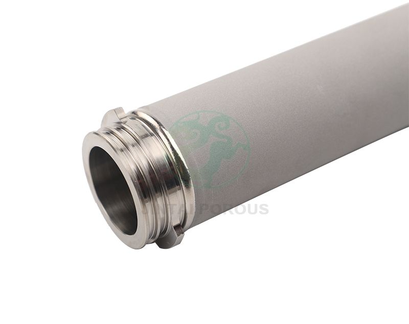
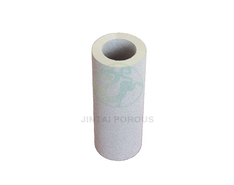
Sintered porous metal spargers are made by forming and heating metal powder under controlled conditions. The process creates a strong body with connected pores. Stainless steel is common because it offers mechanical strength, corrosion resistance, and repeated cleaning capability.
Compared with drilled holes, porous metal provides many release points across the active surface. This can create better gas distribution and a higher gas-liquid contact area. Compared with some fragile membrane materials, metal can provide better resistance to heat, pressure, and mechanical handling.
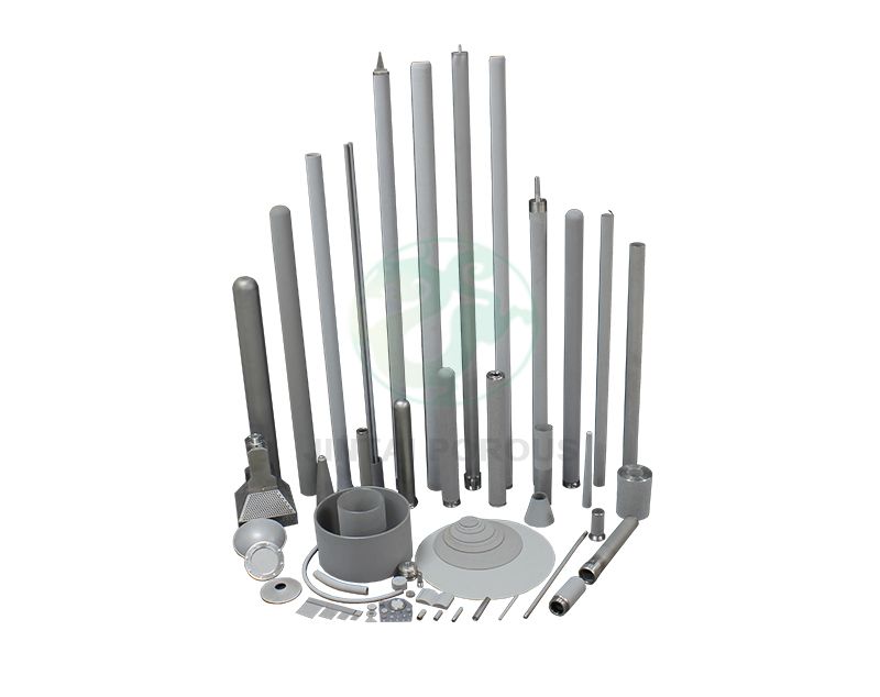
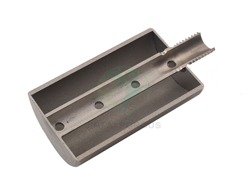
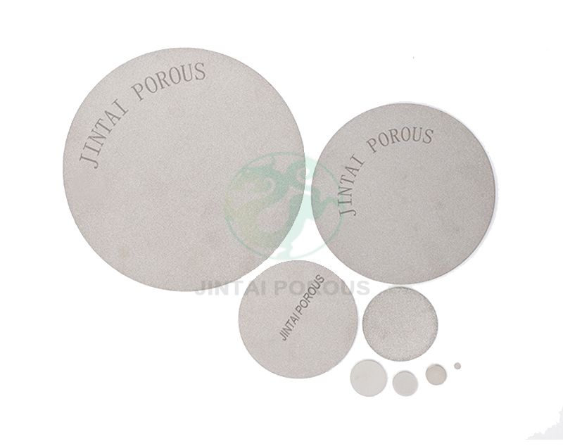
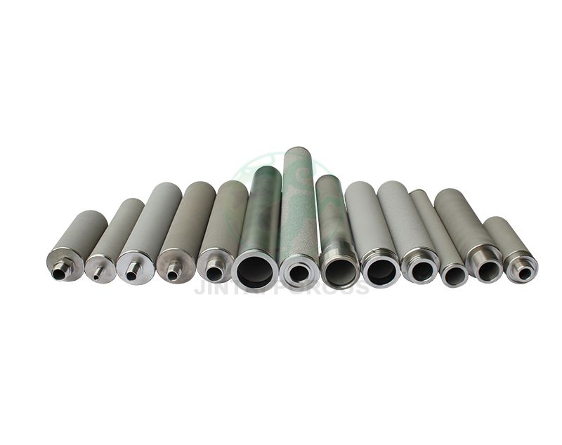
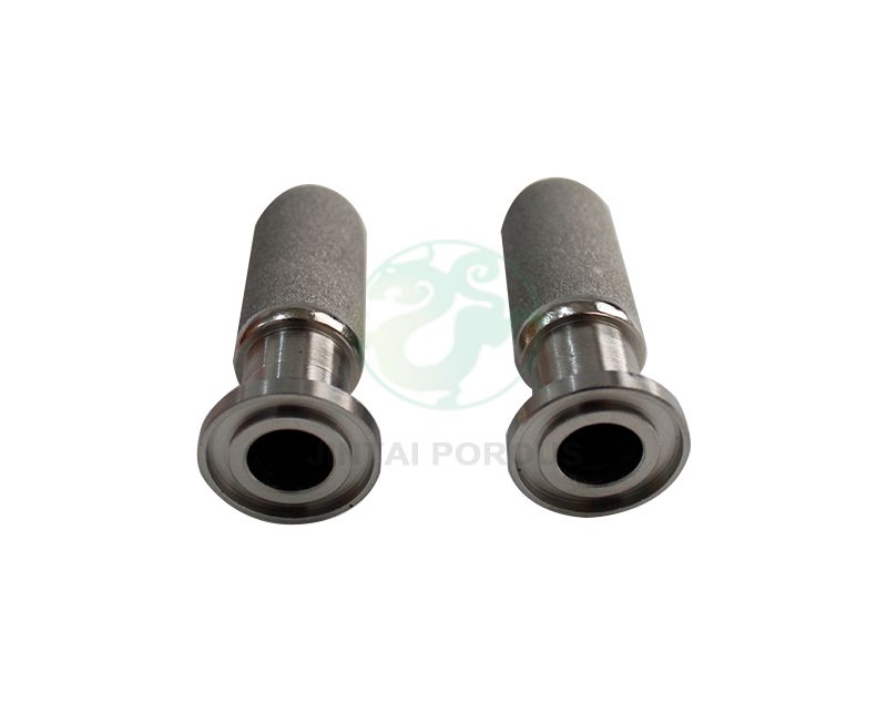
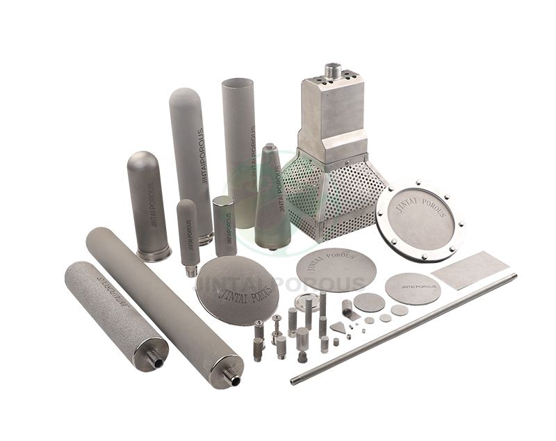
JINTAI can configure porous metal spargers by material, shape, pore grade, connection, and active area. Common forms include tubes, discs, plates, and custom assemblies. The correct design should be based on gas flow, liquid conditions, pressure, cleaning method, and installation space.
8. Why Sintered Porous Metal Is Useful
9. Testing Checklist for Overseas Buyers and Distributors
Before placing a production order, request the technical data needed to compare different sparger models. A clear specification reduces installation risk and helps the end user select the correct compressor or blower.
- Gas type and maximum gas flow
- Normal and maximum operating pressure
- Active sparger area
- Porous metal material and pore range
- Connection size and installation direction
- Liquid temperature and viscosity
- Required bubble size or transfer target
- Cleaning and sterilization method
- Required test report and dimensional inspection
- Replacement and maintenance schedule
Ask for a sample test when the liquid is expensive, viscous, corrosive, or difficult to clean. A short test can show whether the selected gas flow rate creates stable bubbles across the full sparger surface.
10. Final Design Rule
The best gas flow rate is not the highest possible rate. It is the rate that provides the required gas transfer and mixing without excessive bubble coalescence, foam, pressure, or energy use.
Start with a moderate gas flux, such as 0.05 to 0.30 Nm3/h/cm2, then adjust the flow while watching bubble size and distribution. If bubbles become large, reduce the flow or increase the sparger area. If gas distribution is weak, check pressure, pore blockage, and inlet design before simply increasing the flow.
For a reliable porous metal sparger system, treat gas flow rate, pore size, pressure drop, liquid properties, and active area as one design group. JINTAI can use these process values to recommend a suitable sintered porous metal sparger for aeration, fermentation, wastewater treatment, gas stripping, chemical reaction, and other gas-liquid applications.