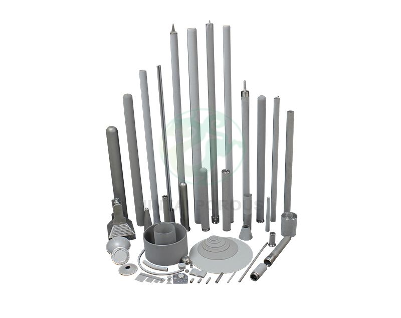
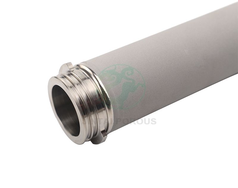
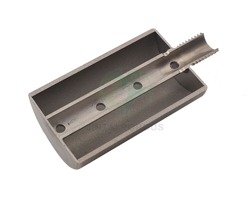
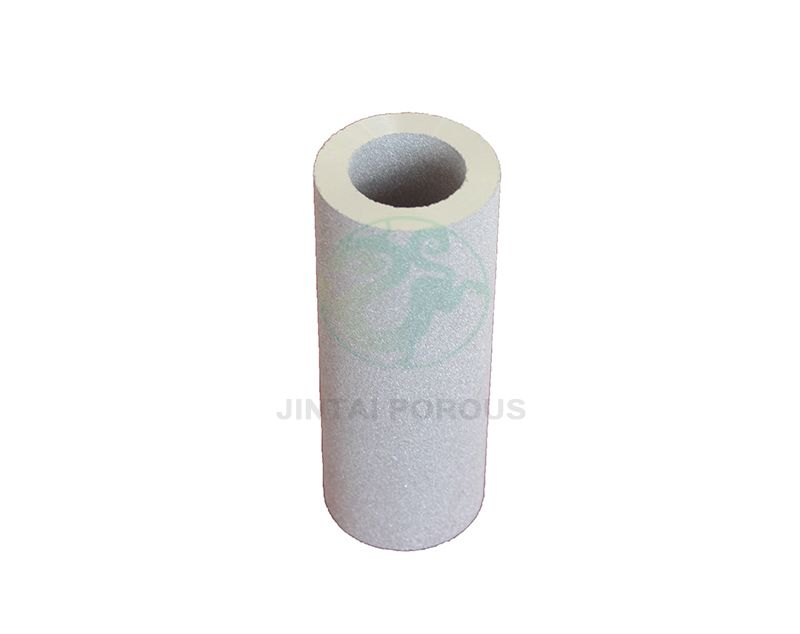
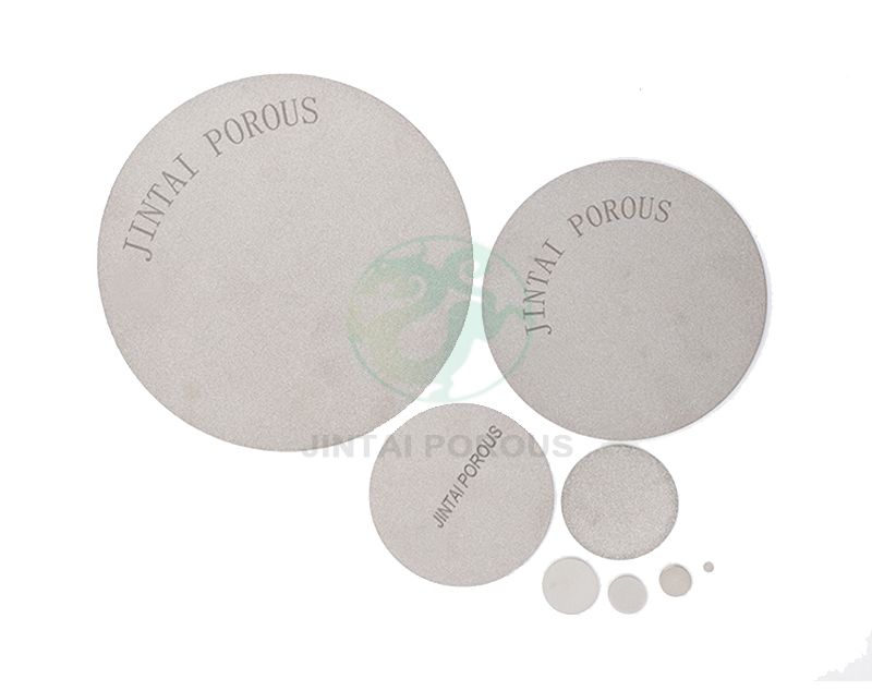
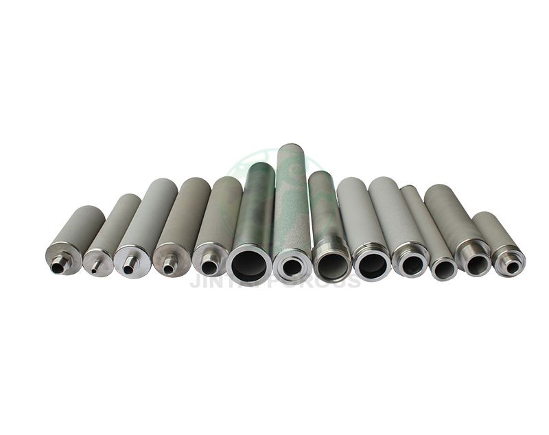
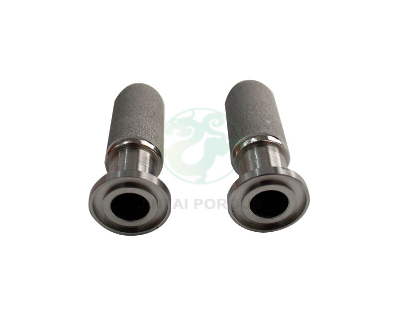
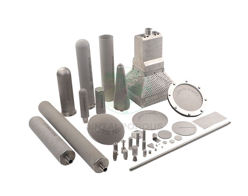
Sintered Porous Metal Spargers are used to disperse gas into liquids, create fine bubbles, improve mass transfer, and support reliable mixing. However, liquid pressure directly affects gas flow, bubble size, pressure drop, gas distribution, and operating cost. This guide explains how liquid pressure changes sparger performance and provides a step-by-step method for selecting and validating a sparger. It is designed to help engineers, plant operators, and purchasing teams compare suppliers such as JINTAI with greater confidence.
Liquid pressure changes the way a sparger produces bubbles
Liquid pressure determines the gas pressure required for operation
Gas must enter the sparger at a pressure higher than the liquid pressure at the sparger surface. The gas supply must overcome several pressure components before it can pass through the porous material.
The minimum required gas pressure can be estimated with this relationship:
Required gas pressure = liquid static pressure + sparger pressure drop + piping losses + control margin
Liquid static pressure usually increases with installation depth. A sparger installed deeper in a tank requires more gas pressure than a sparger installed near the liquid surface.
For a water-like liquid, the approximate hydrostatic pressure is:
Hydrostatic pressure in kPa = liquid density in kg/m3 x gravity in m/s2 x liquid depth in m / 1000
For example, a sparger installed 3 meters below the liquid surface in water experiences approximately 29.4 kPa of hydrostatic pressure before friction and porous media resistance are considered.
Higher liquid pressure can reduce gas flow through the sparger
When the liquid pressure increases while gas supply pressure remains constant, the pressure difference across the sparger becomes smaller. A smaller pressure difference usually reduces gas flow.
Reduced gas flow can cause:
- Lower oxygen transfer or stripping performance.
- Fewer bubbles entering the liquid.
- Uneven gas distribution across the sparger surface.
- Longer processing time.
- Higher risk of unstable operation at low gas flow.
Pressure affects bubble formation and bubble size
A sintered porous metal sparger creates bubbles through many small pores. The final bubble size depends on pore size, gas velocity, liquid properties, surface tension, wettability, and pressure difference.
Higher liquid pressure may compress the gas before it exits the sparger. The gas volume decreases as pressure rises, so the actual gas volume inside the liquid can be lower than the flowmeter reading at the gas inlet.
In general:
- A moderate pressure difference can support stable bubble formation.
- An excessive pressure difference can produce higher gas velocity and larger or less uniform bubbles.
- Insufficient pressure difference can cause weak or intermittent bubbling.
- Uneven pressure along a long sparger can create active and inactive zones.
Pressure drop must be calculated before choosing a sparger
Separate liquid pressure from sparger pressure drop
Liquid pressure is the pressure surrounding the sparger. Sparger pressure drop is the pressure lost as gas passes through the porous metal. These values are related during operation but should not be treated as the same value.
The total gas pressure requirement should include:
- Hydrostatic pressure from liquid depth.
- Pressure caused by liquid density.
- Pressure drop through the porous metal.
- Pressure loss in gas tubing and valves.
- Pressure loss through filters, regulators, and flow controllers.
- A practical operating margin.
Use the correct gas flow basis
Gas flow may be reported as standard flow or actual flow. Standard flow is corrected to a reference pressure and temperature. Actual flow is the gas volume under operating conditions inside the pipe or tank.
Purchasing teams should confirm the following information before comparing quotes:
- Gas type, such as air, oxygen, nitrogen, carbon dioxide, hydrogen, or another process gas.
- Standard flow rate and actual flow rate.
- Operating pressure at the gas inlet.
- Liquid depth above the sparger.
- Liquid temperature and viscosity.
- Liquid density and surface tension.
- Required bubble size or mass transfer target.
- Required operating hours and cleaning frequency.
Allow enough pressure margin without overpressurizing the system
A small pressure margin helps compensate for changes in liquid level, temperature, fouling, and piping resistance. However, excessive pressure can increase energy consumption and may damage the sparger, fittings, tank, or seals.
A practical design review should confirm:
- The blower or gas source can supply the required pressure at the required flow rate.
- The tank and connected piping are rated for the maximum gas pressure.
- The sparger has a stated maximum operating pressure.
- The gas control valve can regulate the system without constant hunting.
- A pressure relief device is installed where required.
Follow a step-by-step method to evaluate pressure effects
First step: Define the process conditions
Record the real operating conditions instead of relying only on nominal equipment data.
- Measure the minimum, normal, and maximum liquid level above the sparger.
- Record the liquid density at the operating temperature.
- Record the liquid viscosity and surface tension if available.
- Identify whether the liquid contains solids, oil, proteins, polymers, salts, or other fouling materials.
- Confirm the gas type and gas purity requirement.
- Define the desired gas flow range.
- Define the required bubble size, transfer rate, stripping rate, or mixing result.
Second step: Calculate the pressure at the sparger location
- Measure the vertical distance from the liquid surface to the centerline of the sparger.
- Multiply liquid density by gravity and liquid depth.
- Convert the result to the pressure unit used by the plant.
- Repeat the calculation for minimum and maximum liquid levels.
- Add any vessel backpressure if the tank is closed or pressurized.
For a closed tank, the pressure surrounding the sparger is the sum of liquid hydrostatic pressure and vessel gas-space pressure.
Third step: Determine the required pressure drop through the sparger
- Obtain the sparger pressure drop curve from the supplier.
- Check whether the curve is based on air, nitrogen, oxygen, or another gas.
- Confirm the test temperature and reference pressure.
- Compare the pressure drop at minimum, normal, and maximum gas flow.
- Check whether the pressure drop remains stable across the intended operating range.
- Reject data that does not identify pore size, active area, gas type, or test conditions.
Fourth step: Check gas source capacity
- Calculate the total required pressure at the sparger inlet.
- Compare this pressure with the blower or compressor discharge pressure.
- Subtract pressure losses from hoses, pipes, valves, filters, and flowmeters.
- Confirm that the gas source still provides the required flow at the calculated pressure.
- Check whether multiple spargers will operate at the same time.
- Confirm that the gas header can distribute flow evenly to every branch.
Fifth step: Test the sparger at operating pressure
- Install the sparger at the intended depth or use a test vessel with equivalent backpressure.
- Fill the vessel with the actual process liquid or a validated substitute.
- Start the gas flow at the lowest planned operating rate.
- Record inlet gas pressure, liquid level, gas flow, temperature, and visual bubble behavior.
- Increase gas flow in controlled increments.
- Record the pressure drop and flow stability at each operating point.
- Repeat the test at the highest expected liquid level.
- Inspect the sparger for dead zones, large bubbles, leakage, vibration, and uneven distribution.
Sixth step: Compare performance against the process target
Do not select a sparger only because it produces visible bubbles. Compare the measured result with the process requirement.
- Gas transfer rate.
- Gas utilization efficiency.
- Bubble size and distribution.
- Pressure stability.
- Energy consumption.
- Cleaning interval.
- Expected service life.
- Maintenance time and replacement cost.
Use the right tools to measure liquid pressure and sparger performance
Required process measurement tools
- Calibrated pressure gauge or pressure transducer for the gas inlet.
- Differential pressure gauge for measuring pressure across the sparger.
- Liquid level gauge, ruler, or calibrated level transmitter.
- Gas flowmeter suitable for the gas type and expected pressure.
- Temperature sensor for gas and liquid temperature.
- Density measurement equipment or reliable liquid density data.
- Viscosity measurement equipment when the liquid is thick or non-Newtonian.
- Leak detection solution or an approved leak testing method.
- Data logger or spreadsheet for recording pressure and flow readings.
Useful installation and inspection tools
- Torque wrench for compression fittings and flange bolts.
- Thread sealant compatible with the gas and process liquid.
- Clean installation gloves and lint-free cleaning materials.
- Calipers for checking critical dimensions.
- Leveling tools for confirming sparger alignment.
- Inspection light for checking welds, fittings, and porous surfaces.
- Replacement gaskets and approved spare seals.
Use compatible instruments for reliable results
A pressure gauge that is too large in range may not show small changes accurately. A flowmeter calibrated for standard conditions may also create confusion when the process requires actual flow.
Before testing:
- Confirm pressure gauge calibration status.
- Use the correct pressure range for the expected operating pressure.
- Install the pressure measurement point as close to the sparger as practical.
- Record whether flow is reported as standard or actual flow.
- Use the same units in calculations and supplier comparisons.
- Document the test liquid and temperature.
Choose sparger specifications that match the pressure conditions
Select pore size based on process performance
Smaller pores can support finer bubbles, but they may also create a higher pressure drop and greater sensitivity to blockage. Larger pores may require less pressure but can produce larger bubbles and lower interfacial area.
When comparing Sintered Porous Metal Spargers, review:
- Nominal pore size.
- Pore size distribution.
- Porosity.
- Permeability.
- Active sparging area.
- Material grade.
- Wall thickness.
- Maximum operating pressure.
- Recommended cleaning method.
Select the active area according to gas flow
A sparger with insufficient active area may require excessive gas velocity and pressure. This can lead to uneven bubbling, high energy consumption, and premature fouling.
A sparger with excessive active area may increase equipment cost without improving process performance. The correct area should be selected using the target gas flux and supplier pressure drop data.
Ask the supplier to provide:
- Recommended gas flow per unit of active area.
- Pressure drop at the minimum and maximum gas flow.
- Expected bubble size range under the specified liquid conditions.
- Maximum allowable gas velocity.
- Test data from a similar liquid or application.
Select materials for pressure, corrosion, and cleaning requirements
Liquid pressure is only one part of mechanical reliability. The porous metal, support tube, welds, fittings, and seals must all withstand the process environment.
Review the following material requirements:
- Corrosion resistance in the process liquid.
- Compatibility with oxygen, ozone, solvents, acids, or alkaline cleaning agents.
- Resistance to thermal cycling.
- Resistance to vibration and repeated pressure changes.
- Weld quality and weld inspection records.
- Surface finish and cleanability.
- Traceability of raw materials and finished components.
Purchasing teams need more than a low initial price
Confirm performance data before requesting a final quotation
A common purchasing problem is comparing products with incomplete or inconsistent specifications. One supplier may quote a pressure drop at standard gas flow, while another may quote actual flow at operating pressure. The numbers may appear comparable even when they are not.
Request the following information in every quotation:
- Sparger dimensions and active area.
- Material grade and material certificates.
- Nominal pore size and tolerance.
- Gas type used for performance testing.
- Pressure drop at defined gas flow rates.
- Maximum operating pressure.
- Recommended liquid depth range.
- Connection type and installation orientation.
- Cleaning and maintenance instructions.
- Inspection and test certificates.
- Lead time and spare parts availability.
- Warranty terms and technical support scope.
Evaluate total cost of ownership
The lowest purchase price may not be the lowest operating cost. A sparger that needs higher gas pressure can increase blower power. A sparger that fouls quickly can increase labor and downtime.
Include these costs in the purchasing evaluation:
- Initial equipment price.
- Shipping and installation cost.
- Gas compression or blower energy.
- Cleaning chemicals and labor.
- Replacement parts.
- Production downtime.
- Inspection and calibration.
- Expected service life.
Use a supplier comparison scorecard
A scorecard helps the purchasing group balance technical performance, commercial risk, and service support.
| Evaluation category |
Questions to ask |
| Pressure performance |
Does the supplier provide pressure drop data at the required flow and liquid pressure? |
| Material quality |
Are material certificates and traceability documents available? |
| Application support |
Can the supplier help verify sizing, gas flow, and installation depth? |
| Quality control |
Are permeability, leak, dimensional, and weld inspections documented? |
| Maintenance |
Are cleaning procedures and replacement parts clearly defined? |
| Delivery risk |
Are lead times, production capacity, and spare inventory reliable? |
| Total cost |
What are the expected energy, cleaning, and replacement costs? |
JINTAI can support the technical review by matching pore structure, material, dimensions, and connection design to the actual gas flow and liquid pressure conditions. Buyers should still request application-specific test data before approving a production order.
Install and operate the sparger in a controlled sequence
First step: Inspect the sparger before installation
- Check the porous surface for dents, scratches, contamination, or blocked areas.
- Confirm the dimensions against the approved drawing.
- Verify the material and connection type.
- Inspect welds, seals, gaskets, and support brackets.
- Confirm that protective packaging has not left fibers or particles on the sparging surface.
Second step: Install the sparger at the specified position
- Place the sparger at the designed liquid depth.
- Keep the sparger level unless the design specifically requires another orientation.
- Prevent contact with tank walls, agitator blades, heating coils, or other equipment.
- Use supports that do not block the active porous surface.
- Install the correct gasket or seal for the gas and liquid service.
- Tighten fittings to the specified torque.
- Confirm that the gas line slopes or drains as required to prevent liquid accumulation.
Third step: Perform a low-pressure leak test
- Close the tank outlet or establish the required test condition.
- Apply gas at a low pressure below the normal operating pressure.
- Inspect all connections, welds, valves, and fittings.
- Check for unexpected pressure decay.
- Stop the test and repair leaks before increasing pressure.
Fourth step: Start gas flow gradually
- Open the gas isolation valve slowly.
- Confirm that pressure rises smoothly.
- Start below the normal gas flow rate.
- Check for uniform bubbling across the active area.
- Increase flow gradually until the target operating point is reached.
- Record inlet pressure and flow after the system stabilizes.
Fifth step: Verify operation at different liquid levels
- Test the minimum liquid level.
- Test the normal operating liquid level.
- Test the maximum expected liquid level.
- Record the gas pressure needed at each level.
- Confirm that the gas source and control valve can maintain stable flow in all cases.
- Adjust the control strategy if the pressure difference changes significantly.
Avoid common pressure-related sparger mistakes
Mistake one: Selecting a sparger only by pore size
Pore size alone does not determine performance. A sparger with small pores may require more pressure and may be unsuitable for a weak blower or a dirty liquid. Review pore size together with permeability, active area, pressure drop, and fouling behavior.
Mistake two: Ignoring liquid depth
Using surface pressure instead of pressure at the sparger location can result in an undersized gas source. Always calculate hydrostatic pressure using the maximum liquid depth and liquid density.
Mistake three: Using standard flow data as actual flow
Gas volume changes with pressure and temperature. Confirm the reference conditions for every flowmeter and supplier test curve before making a performance comparison.
Mistake four: Operating too close to the pressure limit
A system that operates continuously near the maximum pressure may experience unstable control, seal leakage, fatigue, or equipment damage. Maintain a reasonable margin between normal operating pressure and the rated limit.
Mistake five: Increasing gas pressure to solve poor distribution
Poor distribution may be caused by blocked pores, incorrect installation, unequal header resistance, liquid entering the gas line, or an improperly sized sparger. Increasing pressure without identifying the cause can increase energy use and damage the equipment.
Mistake six: Cleaning the porous surface incorrectly
Harsh mechanical brushing, unapproved chemicals, or excessive thermal shock can change pore structure or damage the surface. Use the supplier's cleaning procedure and confirm chemical compatibility before cleaning.
Mistake seven: Failing to test at real operating conditions
A sparger that performs well in clean water may behave differently in a viscous, contaminated, corrosive, or foaming process liquid. Validate the design using the actual liquid or a representative substitute whenever possible.
Troubleshoot unstable gas flow and pressure changes
When gas flow is lower than expected
Check the following conditions in order:
- Confirm that the gas source is producing the required pressure and flow.
- Check whether the liquid level is higher than the design value.
- Inspect filters, regulators, valves, and tubing for restrictions.
- Check for liquid trapped in the gas line.
- Inspect the sparger for fouling or blocked pores.
- Compare the measured pressure drop with the original supplier data.
- Confirm that the flowmeter is calibrated for the gas and pressure conditions.
When bubbles are large or uneven
- Check whether gas flow is above the recommended gas flux.
- Inspect the gas header for unequal branch resistance.
- Check whether the sparger is level and correctly supported.
- Look for blocked sections or damaged porous media.
- Confirm that liquid properties have not changed significantly.
- Check whether the sparger pore size matches the process target.
When pressure increases during operation
A gradual pressure increase often indicates fouling or restricted flow. Record pressure at a fixed gas flow so that trends can be compared over time.
Recommended actions include:
- Review the cleaning interval.
- Inspect the liquid for solids or precipitated material.
- Check upstream gas filters for contamination.
- Compare pressure data with previous operating cycles.
- Clean according to the approved procedure.
- Replace the sparger if pressure does not return to an acceptable range.
Use this final checklist before approving a purchase
Technical approval checklist
- Liquid depth and density are defined.
- Gas type and gas flow range are defined.
- Pressure at the sparger location is calculated.
- Sparger pressure drop data is available.
- Gas source capacity is verified at operating pressure.
- Pore size and active area match the process target.
- Material compatibility is confirmed.
- Maximum operating pressure is documented.
- Installation dimensions and connections are approved.
- Cleaning and maintenance procedures are available.
- Performance testing is planned for representative conditions.
Commercial approval checklist
- The quotation identifies all product specifications.
- Supplier test data uses clearly defined flow and pressure conditions.
- Quality documents and inspection records are included.
- Lead time is acceptable for the project schedule.
- Spare parts and replacement units are available.
- Warranty terms are clearly stated.
- Technical support is available during installation and commissioning.
- Total cost of ownership has been compared with alternative designs.
Liquid pressure should be treated as a primary design parameter, not a minor installation detail. By calculating pressure at the sparger, reviewing pressure drop data, testing the system step by step, and comparing total ownership cost, purchasing teams can reduce performance risk and avoid costly rework. With application-specific sizing, material selection, and test documentation from JINTAI, Sintered Porous Metal Spargers can deliver stable gas distribution under demanding liquid pressure conditions.