
October 14, 2026

Porous metal components help fluidization systems spread gas through powder beds with better control and less maintenance. Poor gas distribution can cause dead zones, channeling, uneven heating, and unstable particle movement. A well-designed fluidizing bed distributor improves gas distribution across the working area. It can also support stable particle fluidization in chemical, food, pharmaceutical, and battery material processes. Sintered porous metal provides controlled pore size, high mechanical strength, and resistance to heat and many chemicals. A porous metal sparger can create fine bubble formation in reactors and mixing vessels. This article explains how to select, design, test, and maintain these components for industrial use.
Porous metal components are used in fluidization systems to distribute gas or liquid evenly through a bed of solid particles. Sintered stainless steel, nickel, bronze, and other porous metals offer controlled pore sizes, strong mechanical performance, and resistance to heat and corrosion. The correct component depends on the gas velocity, powder size, operating temperature, pressure drop, chemical environment, and required cleaning method. A properly designed porous metal distributor can reduce channeling, improve heat transfer, support stable fluidization, and extend service life.
Porous metal components are made by compacting metal powder and heating it below the metal's melting point. This process is called sintering. It creates a solid structure with connected pores. The pores allow gas or liquid to pass through the material while the metal body supports pressure, vibration, and repeated cleaning.
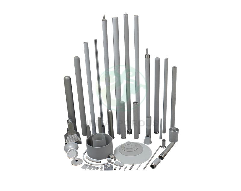
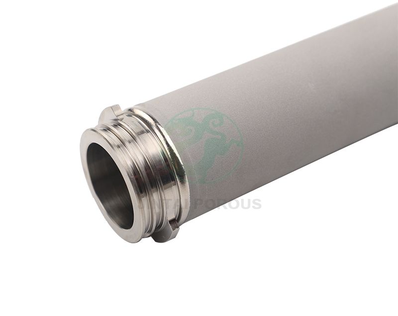
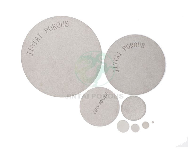
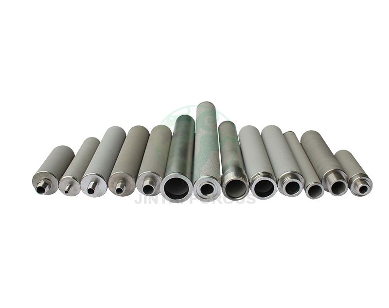
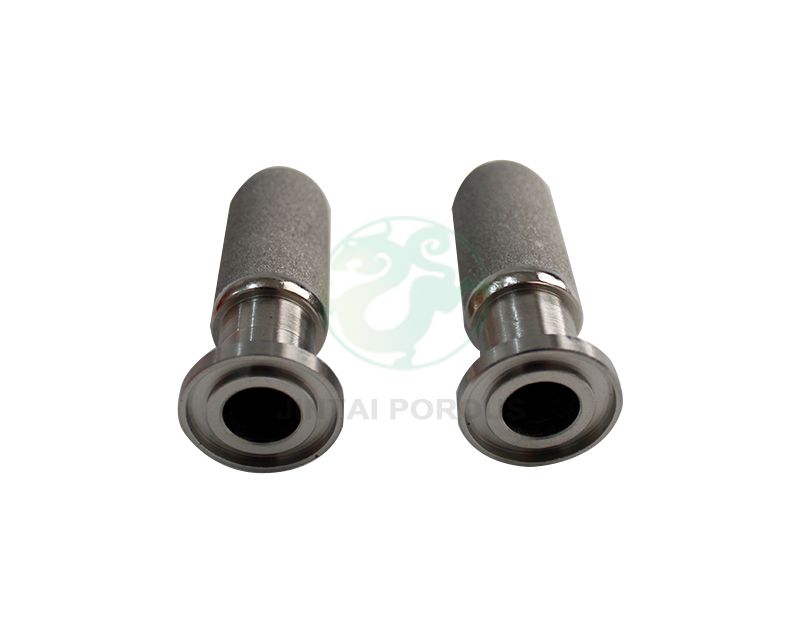
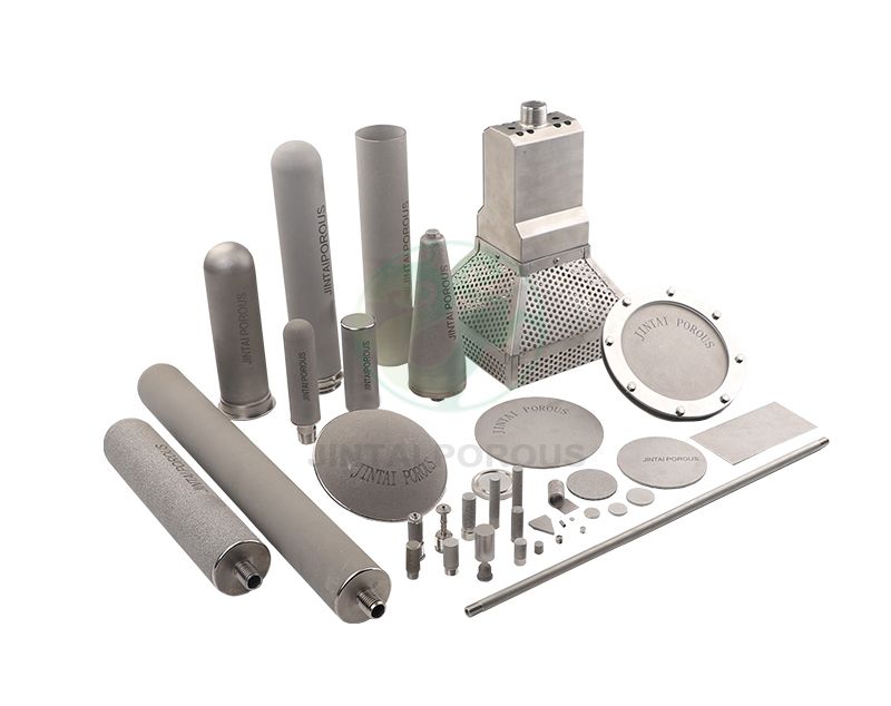
Common products include:
Metal powder is selected by alloy, particle size, and shape. The powder is then compacted in a mold. During sintering, the particles bond together and form a network of open pores.
The final component can be designed with:
These values depend on the powder grade, forming pressure, sintering temperature, and final machining process.
A fluidization system must move gas through solid particles at a controlled rate. The distributor is one of the most important parts of the system. If the distributor produces uneven flow, the bed may develop channels. Some areas receive too much gas, while other areas receive too little.
A sintered porous metal distributor provides many small flow paths across its surface. This supports more uniform gas distribution than a simple open pipe or a plate with a small number of drilled holes.
Uniform flow can improve:
Porous metal is stronger and more rigid than many polymer membranes. Stainless steel components can support pressure differences, thermal cycling, and vibration. A typical sintered stainless steel gas diffuser can operate in high-temperature applications when the alloy and design are suitable.
Actual service temperature depends on the alloy, gas chemistry, load, sealing method, and thermal cycle. For example, 316L stainless steel is often selected for corrosion resistance in moderate temperature systems. Nickel alloys may be considered for higher temperature or more aggressive chemical service.
Many sintered metal components can be cleaned by backwashing, air pulsing, ultrasonic cleaning, or controlled chemical cleaning. Their rigid pore structure helps prevent permanent deformation during cleaning.
Cleaning conditions must match the alloy. Chloride-rich chemicals can damage some stainless steels. Strong acids and caustic solutions may also affect the component if concentration, temperature, and exposure time are not controlled.
| Component | Main Function | Common Materials | Typical Application |
|---|---|---|---|
| Distributor plate | Spreads gas under a powder bed | 316L stainless steel, nickel, bronze | Fluidized beds and dryers |
| Sparger tube | Introduces gas into a liquid or powder process | 316L stainless steel, Hastelloy, nickel | Chemical reactors and aeration systems |
| Porous disc | Creates localized gas flow | Stainless steel, bronze | Small vessels and laboratory equipment |
| Diffuser panel | Provides large-area gas distribution | Stainless steel and nickel alloys | Large powder handling systems |
| Porous cartridge | Filters or vents gas during processing | Stainless steel, bronze | Powder transfer and gas filtration |
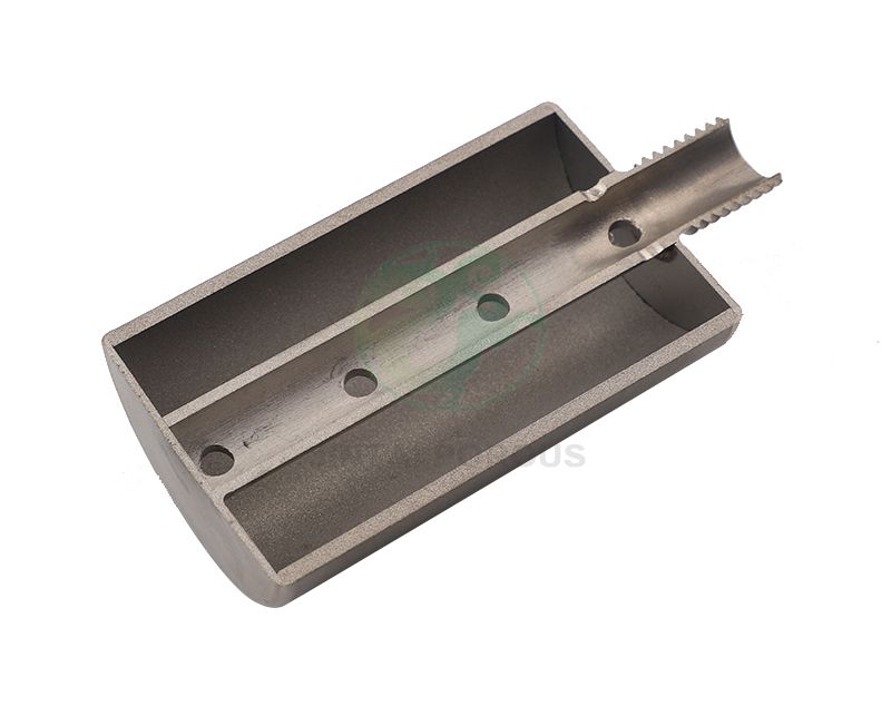
A porous metal distributor plate for fluidized beds is installed between the gas plenum and the powder chamber. It must provide enough pressure drop to balance flow across the surface. It must also resist the weight and movement of the powder bed.
Plate design may include:
A porous metal sparger for chemical reactors uses small pores to produce a controlled gas stream. The pore size affects bubble size, flow resistance, and the risk of blockage. A sparger must be matched to the gas, liquid, solids content, and cleaning cycle.
Pore size affects flow rate and particle retention. Smaller pores usually create higher pressure drop. Larger pores usually provide greater flow capacity but may allow fine particles to enter the structure.
Manufacturers may measure air permeability under a defined pressure. A useful specification should include the test gas, test pressure, exposed area, temperature, and flow rate. Permeability results without test conditions are difficult to compare.
The distributor should create a stable pressure drop without consuming excessive blower energy. In many systems, the distributor pressure drop is designed as a controlled part of the total system pressure. A practical preliminary range may be 5 kPa to 30 kPa, but the correct value depends on powder properties and operating conditions.
Important factors include:
| Material | Strengths | Limitations | Typical Use |
|---|---|---|---|
| 316L stainless steel | Good corrosion resistance and weldability | Not suitable for every high-temperature or chloride service | Food, pharmaceutical, chemical, and general process equipment |
| 304 stainless steel | Cost-effective and easy to fabricate | Lower corrosion resistance than 316L in some environments | Dry gas and mild process conditions |
| Bronze | Good machinability and useful permeability | Limited compatibility with some chemicals and temperatures | Low-temperature gas and pneumatic equipment |
| Nickel alloys | Strong performance in high-temperature or corrosive service | Higher material and processing cost | High-temperature fluidization and chemical processing |
Use the following process before placing an order for custom porous metal components for powder processing.
Reliable porous metal components require control at each production stage. JINTAI can structure a project around material verification, pore control, dimensional inspection, and flow testing.
| Inspection Item | Method or Standard | Example Control Metric |
|---|---|---|
| Material identity | Material certificate and positive material identification | Alloy grade matches the approved drawing |
| Bubble point | ASTM F316 or an agreed internal method | Result remains within the approved pore range |
| Air permeability | Controlled air test with recorded pressure and area | Flow rate within the approved tolerance band |
| Porosity | Density calculation or liquid displacement method | Typical target range of 25 percent to 45 percent |
| Dimensions | Coordinate measuring machine, caliper, micrometer, or gauge | Drawing tolerance, often plus or minus 0.05 mm for machined features |
| Pressure drop | Flow bench test at defined gas rates | Stable result at low, nominal, and high flow |
| Surface condition | Visual inspection and surface roughness measurement | Free of cracks, loose powder, dents, and blocked areas |
A practical JINTAI development program can use three prototype rounds. The first round confirms material, shape, and basic flow. The second round checks pressure drop, powder behavior, and cleaning performance. The third round confirms the production drawing and inspection limits.
Each round should record at least five flow points. These may include 20 percent, 40 percent, 60 percent, 80 percent, and 100 percent of the design gas flow. A test report should include the component serial number, test temperature, gas pressure, flow rate, pressure drop, and test duration.
For implementation, a controlled pilot run may use one to three production units before a larger batch. The pilot should run for a defined period, such as 100 to 500 operating hours, when the process allows. Operators should record bed pressure, gas flow, product quality, cleaning frequency, and visible signs of channeling.
| Distributor Type | Flow Control | Mechanical Strength | Cleaning | Design Flexibility |
|---|---|---|---|---|
| Sintered porous metal | High when pore size and permeability are controlled | High | Backwash, air pulse, ultrasonic, or chemical methods may be used | High for custom shapes |
| Perforated plate | Depends on hole layout and pressure balance | High | Usually simple | High, but local flow can vary |
| Wire mesh | Good for some low-pressure systems | Medium | Can be difficult if powder enters the mesh | Medium |
| Polymer membrane | Good in selected low-temperature applications | Lower at high temperature and high load | Limited by chemical and thermal compatibility | Medium |
Channeling occurs when gas follows a few low-resistance paths through the powder bed. It can result from an uneven distributor, poor sealing, blocked pores, or an incorrect gas velocity.
Possible solutions include:
Excessive pressure drop may result from pores that are too small, surface contamination, powder intrusion, or an undersized flow area. Compare clean and used test results. A rise of 10 percent to 20 percent may indicate early fouling, depending on the process baseline.
Powder leakage can occur through cracks, poor seals, or pores that are too large for the application. Inspect the sealing surface and perform a bubble point or retention test. The test method should match the powder size and process risk.
Large plates may bend during heating because of thermal expansion. Use suitable support spacing, controlled heating and cooling rates, and an alloy with the required thermal performance. Record flatness before and after thermal testing.
Porous metal components are used in many fluidization and gas distribution applications.
Regular inspection helps maintain stable performance. Create a baseline when the component is new. Compare future results with this baseline.
Do not use a wire brush or sharp tool on the porous surface unless the manufacturer approves it. Mechanical damage can change the pore structure and create leakage paths.
Porous metal components for fluidization systems provide controlled gas distribution, strong mechanical support, and repeatable process performance. Sintered stainless steel, bronze, nickel, and other alloys can be designed for different pore sizes, temperatures, pressure drops, and cleaning cycles. The best result comes from matching the distributor to the powder, gas, operating velocity, chemical environment, and equipment structure. Careful prototyping, flow testing, dimensional inspection, and maintenance records reduce the risk of channeling and early failure. With a defined engineering and quality plan, JINTAI can support reliable sintered porous metal components for fluidized beds, spargers, diffusers, and custom powder processing equipment.