
July 28, 2026
Gas delivery inside semiconductor equipment must be accurately controlled from the supply line to the process chamber. Even when a mass flow controller delivers the correct total gas volume, the process may still be affected if gas enters the chamber as a concentrated jet, creates turbulence or reaches different wafer areas at different velocities.
A porous metal gas diffuser divides an incoming gas stream among many small flow paths. This helps reduce localized impact, equalize chamber pressure and distribute gas more consistently across the process area.
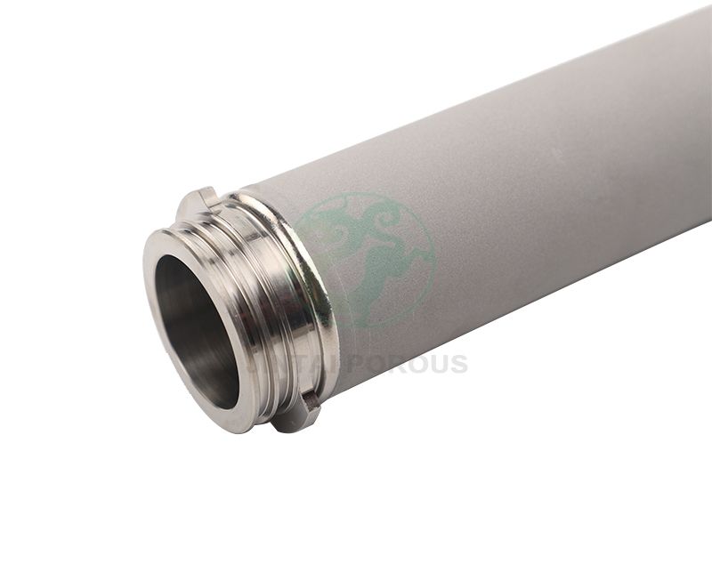
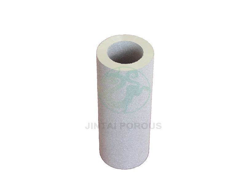
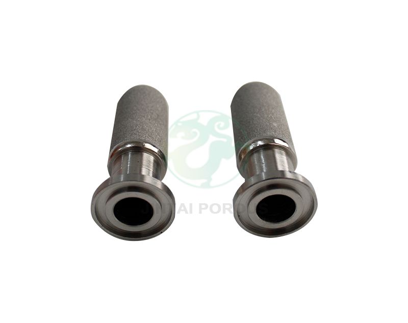
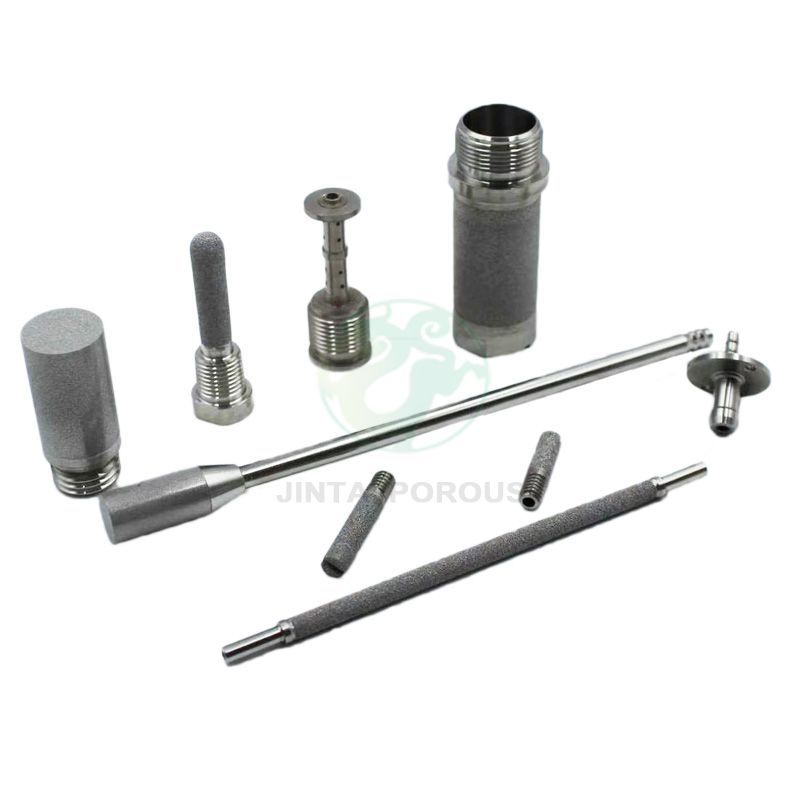
JINTAI’s metal gas diffuser is designed for semiconductor chambers and high-purity gas systems where rapid diffusion, laminar flow, low disturbance and long-term operating stability are important. The manufacturer also states that its porous structure can capture incoming particles larger than 3 nm.
Semiconductor processes depend on controlled quantities of process, purge and carrier gases. NIST notes that accurate gas metering into process chambers is critical to semiconductor throughput and yield. However, measuring the total flow is only one part of the system; the gas must also be distributed appropriately after entering the chamber.
Uneven chamber flow may contribute to differences in:
Gas concentration across the wafer
Local reaction rates
Etching depth
Deposited-film thickness
Chamber purging time
Particle movement
Temperature distribution
Experimental research on rapid thermal processing found that a showerhead with finer openings produced better gas-flow distribution inside the processing chamber. Other research has linked chamber gas-flow distribution with etch-depth uniformity across large-area wafers.
A diffuser therefore does not replace the mass flow controller. The controller determines how much gas enters the system, while the diffuser influences how that gas is introduced into the chamber.
A conventional open inlet allows gas to enter through one relatively large passage. Depending on pressure, flow rate and chamber geometry, this may create a high-velocity jet directed toward a wafer or another sensitive component.
A porous metal diffuser replaces the single large flow path with an interconnected network of small pores. Gas passes through these pores and exits over a wider surface area.
This structure can perform three related functions:
It creates controlled resistance to the incoming gas.
It divides the flow among numerous small passages.
It reduces the velocity concentration associated with a direct inlet.
The resulting flow pattern can support more gradual gas entry and reduce localized disturbance near the wafer.
The final effect depends on the diffuser’s pore structure, dimensions, position and relationship with the complete chamber design. A diffuser that works correctly in one chamber should not automatically be copied into another chamber with different pressure, volume or inlet geometry.
Many semiconductor processes include repeated pressurization, evacuation and purging stages. The time needed for chamber pressure to stabilize can affect the duration of the overall process cycle.
JINTAI states that its gas diffuser is designed to support rapid pressure equalization between the equipment chamber and the external gas environment. Faster and more controlled equalization can help shorten transition stages and support higher equipment throughput.
However, pressure equalization must be balanced against disturbance. Simply increasing inlet flow may reduce filling time but can also create stronger jets, turbulence or local pressure differences.
A properly specified diffuser should therefore meet both requirements:
Sufficient flow for the required pressure-equalization time
Controlled gas velocity near sensitive chamber components
When comparing diffuser designs, buyers should request pressure-drop and equalization data under their actual inlet and outlet pressure conditions.
Laminar flow describes gas movement in relatively orderly layers rather than irregular turbulent patterns. In semiconductor processing, lower-disturbance flow can help create more predictable conditions near the wafer.
A porous diffuser can encourage distributed flow by releasing gas through many controlled passages instead of one concentrated opening. JINTAI identifies laminar flow and low disturbance as two of the main characteristics of its metal gas diffuser.
Uniform flow is especially relevant to processes such as:
Chemical vapor deposition
Atomic layer deposition
Plasma etching
Chamber purging
Inert-gas protection
Vacuum-chamber venting
Wafer transfer environments
Research on deposition reactors shows that gas inlet configuration and gas-flow conditions can influence film-thickness uniformity. Flow rate, chamber geometry, inlet design and wafer position should therefore be considered together rather than optimized separately.
A concentrated gas jet may disturb particles already present inside the chamber or produce uneven local conditions over the wafer surface.
By spreading the flow over a larger porous area, a metal diffuser can reduce the direct mechanical impact of the incoming gas. This is particularly important when the inlet is positioned close to the wafer or when the chamber has limited space for flow development.
Low-disturbance gas introduction may help reduce:
Direct impingement on the wafer
Localized high gas velocity
Particle resuspension
Flow shadows
Recirculation zones near the inlet
Differences between central and edge regions
The diffuser’s installation position remains important. A well-designed porous element may still perform poorly if installed too close to an obstruction or if the chamber exhaust arrangement creates an unbalanced flow field.
Gas diffusion is the component’s primary function, but the porous structure can also provide a particle-retention effect.
JINTAI states that its gas diffuser can capture particulate impurities larger than 3 nm in the incoming gas stream. This may provide an additional contamination-control barrier immediately before gas enters the chamber.
The filtration claim should be evaluated by asking for:
Test method
Particle size used in testing
Retention efficiency
Test gas
Flow rate
Pressure conditions
Clean pressure drop
Loading capacity
A diffuser should not automatically replace a dedicated high-purity gas filter. If a process has a specified particle-retention requirement, the complete filtration system should be reviewed separately.
A typical arrangement may include:
Gas supply → high-purity gas filter → flow-control component → gas diffuser → process chamber
In this system, the filter controls incoming contamination, the flow-control device sets the gas rate and the diffuser manages final chamber entry.
Although all three components may use porous metal, they should not be treated as interchangeable.
| Component | Primary Purpose | Main Performance Target |
|---|---|---|
| Gas diffuser | Distribute gas inside a chamber | Flow uniformity and pressure equalization |
| High-purity gas filter | Remove particles from a gas stream | Filtration rating and retention efficiency |
| Gas flow restrictor | Limit or stabilize gas flow | Target flow at a specified pressure differential |
A filter inevitably creates some resistance, but it is not necessarily calibrated to provide a precise flow. A restrictor distributes resistance through a porous body, but it is not automatically qualified as a high-efficiency filter. A diffuser may retain particles, but its geometry is primarily developed for chamber flow distribution.
Defining the component’s main function before discussing pore size helps prevent an incorrect specification.
A quotation request should not contain only the diffuser diameter and filtration rating. The manufacturer needs system-level operating information.
Identify the gas or gas mixture, concentration and purity. Gas properties influence flow behavior and pressure drop.
Relevant gases may include:
Nitrogen
Argon
Hydrogen
Helium
Clean dry air
Process-specific gas mixtures
Material compatibility must be checked for reactive or corrosive gases.
Provide minimum, normal and peak flow rates. A diffuser designed only around the maximum value may create unnecessary pressure drop during normal operation.
The supplier needs both inlet and outlet conditions to calculate the differential pressure across the porous element.
Specify whether the system operates under:
Atmospheric pressure
Positive pressure
Partial vacuum
Repeated vacuum-to-atmosphere cycles
State how quickly the chamber must reach its target pressure. This allows the diffuser’s flow capacity to be evaluated against the process-cycle requirement.
A diffuser must provide enough resistance to distribute the gas, but excessive resistance may reduce flow or increase the upstream pressure requirement.
The allowable clean and operating pressure drops should be defined separately when possible.
Provide chamber drawings showing:
Internal volume
Inlet position
Exhaust position
Wafer location
Distance between the diffuser and wafer
Nearby obstructions
Available mounting space
Flow distribution cannot be evaluated reliably without understanding the surrounding chamber geometry.
Temperature can affect gas properties and material selection. State both normal and maximum operating temperatures, including cleaning or bake-out conditions.
Porous metal is suitable for applications requiring dimensional stability, mechanical strength and resistance to repeated pressure cycles.
The diffuser specification should identify:
Porous metal grade
Housing material
Gas-contact materials
Pore structure
Diffuser shape
Welding method
Surface condition
Cleanliness requirements
Connection method
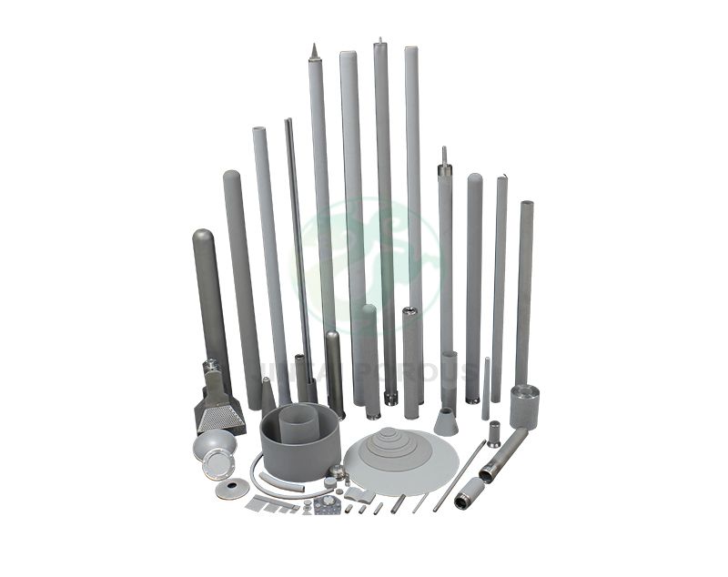
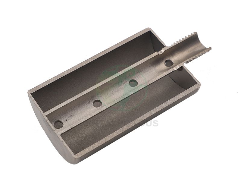
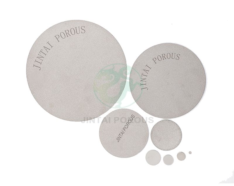
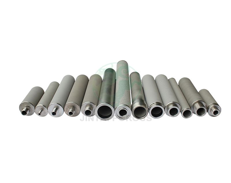
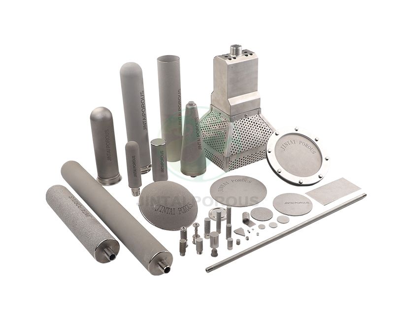
Possible diffuser geometries include discs, tubes, cups, plates and custom-shaped components. The correct form depends on the direction in which the gas needs to be distributed.
A disc may be suitable for axial flow across a chamber inlet, while a cylindrical porous surface may provide radial distribution. The shape should follow the required flow field rather than available catalogue dimensions.
A diffuser installed near a semiconductor wafer must not become a new contamination source.
Buyers should confirm the supplier’s procedures for:
Raw-material control
Sintering
Machining
Welding
Cleaning
Drying
Packaging
Particle inspection
Product traceability
The final cleaning process should be compatible with the application and material. Packaging should prevent the clean porous surface from being contaminated during transportation and installation.
The purchase specification should also clarify whether the component can be touched directly, cleaned again before installation or exposed to ultrasonic cleaning.
The diffuser should be evaluated under conditions that represent the intended equipment as closely as possible.
Useful tests may include:
Gas flow at specified differential pressure
Pressure-drop testing
Chamber equalization time
Leak testing
Flow-uniformity testing
Particle-retention testing
Particle-shedding inspection
Dimensional inspection
Material verification
Pressure-cycle testing
For critical equipment, computational fluid dynamics can help compare diffuser position, surface area and flow direction before producing the final design. Physical chamber testing is still important because seals, internal components and manufacturing tolerances can affect actual performance.
Pore size alone does not define flow capacity, pressure drop or chamber distribution.
The diffuser creates resistance, but precise flow control should be specified and tested separately.
The inlet, exhaust, wafer and diffuser position determine how the gas moves after leaving the porous surface.
Uniform diffusion requires controlled resistance. The supplier must balance flow capacity with distribution performance.
Request the test efficiency and operating conditions behind the stated particle rating.
A technically correct diffuser may still be unsuitable if cleaning and packaging do not meet the process requirements.