
September 24, 2026

Porous Metal Components for High-Temperature Applications help control gas, liquid, heat, and pressure in systems where plastic and standard filter media can fail. A porous metal filter can operate at high temperatures while keeping a stable pore structure. Metal filtration is useful in chemical processing, fuel systems, and industrial gas treatment. Thermal stability is also important because repeated heating and cooling can damage weak materials. Engineers also use sintered metal parts for flame arresting, fluid distribution, and noise reduction. The main question is simple: how can a porous component deliver reliable flow without losing strength at high temperature?
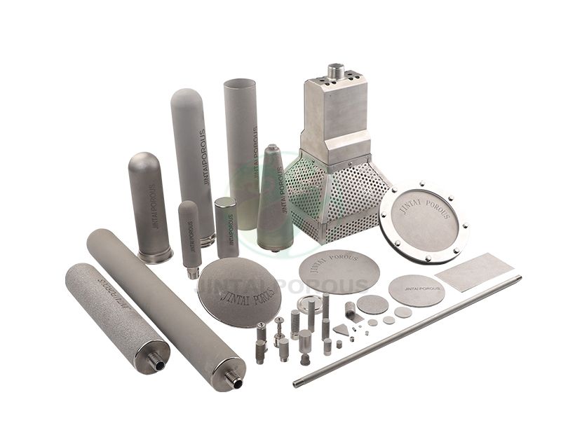
The answer depends on material selection, pore size, wall thickness, operating pressure, and sintering quality. JINTAI develops and manufactures Sintered Porous Metal Components for demanding industrial conditions. These components can be made from stainless steel, nickel alloys, bronze, and other powder metals. A correct design can improve filtration efficiency, reduce maintenance, and extend equipment service life.
Sintered stainless steel and nickel-alloy porous metal components are usually the best choices for high-temperature applications. Stainless steel grades such as 316L are suitable for many systems up to about 500 to 600 degrees C, depending on load, atmosphere, and design. Nickel alloys such as Inconel 600 or Inconel 625 can support higher temperatures and stronger corrosion resistance. The final choice should be based on operating temperature, pressure, chemical exposure, pore size, permeability, and required service life. A qualified supplier should verify the part through dimensional inspection, bubble point testing, flow testing, pressure testing, and material analysis.
Sintered porous metal components start as metal powder. The powder is placed into a mold and compacted under controlled pressure. The compact is then heated below the metal melting point. This process is called sintering. It bonds the particles while leaving connected spaces between them.
The connected spaces form the pore network. The pore network controls gas or liquid flow. Pore size can be adjusted by selecting a powder size range, changing compaction pressure, and controlling the sintering cycle. Common nominal pore ratings range from 0.5 to 100 micrometers. Some special parts use larger pores for high flow rates.
Typical design parameters include:
A smaller pore size usually increases filtration efficiency but also increases pressure drop. A larger pore size improves flow but may allow larger particles to pass. Engineers must balance these two factors instead of selecting the smallest possible pore size.
316L stainless steel is widely used for porous filters, spargers, vent plugs, and flow restrictors. It offers good resistance to moisture, many chemicals, and oxidation in moderate high-temperature service. It is also easy to clean and weld. Many 316L components are used below 500 to 600 degrees C, but the actual limit depends on the atmosphere and mechanical stress.
310 stainless steel contains more chromium and nickel than 316L. It provides better oxidation resistance in elevated-temperature air service. It is often considered for furnace parts, hot gas filtration, and heat treatment equipment. The design team should still review creep, thermal cycling, and chemical compatibility before approving the material.
Nickel alloys are suitable when both heat and corrosion resistance are required. Inconel 600, Inconel 625, and similar nickel-based materials can be used in high-temperature gas filtration, chemical reactors, and aerospace equipment. These alloys generally cost more than stainless steel, but they can provide longer service in severe environments.
Bronze porous parts offer good machinability and flow performance. However, bronze is usually selected for lower-temperature applications than stainless steel and nickel alloys. Titanium may be used when low density and corrosion resistance are important. The material must be checked against the gas, liquid, temperature, pressure, and cleaning method.
| Material | Typical advantage | Common use range | Design concern |
|---|---|---|---|
| 316L stainless steel | Corrosion resistance and cleanability | Moderate to high temperature service, often below 500 to 600 degrees C | Check oxidation and long-term strength |
| 310 stainless steel | Improved oxidation resistance | High-temperature air and furnace service | Review thermal cycling and cost |
| Inconel 600 | Heat and corrosion resistance | High-temperature chemical and gas systems | Higher material and processing cost |
| Inconel 625 | High strength and corrosion resistance | Severe thermal and chemical environments | Requires controlled processing and inspection |
| Bronze | Good flow and machining performance | Lower-temperature filtration and fluid control | Limited high-temperature strength |
Porous metal filters remove dust and solid particles from hot gases. They are used in chemical plants, power equipment, metal processing, and thermal treatment systems. A sintered filter can replace ceramic media when the application needs better impact resistance or a metal connection.
The filter rating must match the particle size. For example, a 5 micrometer nominal filter may be suitable for fine particle control, while a 50 micrometer filter may be selected for prefiltration and high flow. The system designer should also calculate pressure drop at the actual temperature and flow rate.
Porous metal components can remove particles from fuel gas and combustion air. They can also support stable gas distribution in burners. The metal structure withstands vibration and can be cleaned by back-pulsing, liquid washing, or ultrasonic cleaning when the design allows it.
A porous metal flame arrestor can reduce flame propagation through a gas line. The pore structure removes heat from the flame front. The correct pore size, length, gas composition, and flow speed must be verified through application testing. Porous metal diffusers also spread gas through a liquid or process chamber. Uniform bubble distribution can improve reaction control and mixing.
Furnaces use porous metal parts for gas distribution, venting, filtration, and pressure equalization. Stainless steel and nickel alloys are common choices. The component should be designed for thermal expansion. A part that fits at room temperature may become too tight or too loose when heated.
Clean porous metal filters are used in gas delivery and vacuum systems. These applications require low particle release, low outgassing, and consistent pore structure. Electropolishing, cleaning, and controlled packaging may be required. The supplier should define the cleaning method and acceptance limits before production.
| Application | Primary function | Important parameters |
|---|---|---|
| Hot gas filtration | Particle removal | Pore size, pressure drop, dust loading, cleaning method |
| Gas diffuser | Uniform gas distribution | Permeability, bubble size, flow rate, chemical resistance |
| Flame arrestor | Control of flame propagation | Pore size, element length, gas composition, test standard |
| Furnace vent | Pressure equalization | Temperature, thermal expansion, strength, sealing method |
| Vacuum filter | Particle control and gas protection | Cleanliness, outgassing, leak rate, particle release |
Material selection -> Powder preparation -> Tooling and compaction -> Debinding if required -> Controlled sintering -> Calibration or machining -> Cleaning -> Inspection -> Packaging
JINTAI first reviews the operating temperature, pressure, flow rate, fluid type, particle size, connection method, and service life target. The design team also checks whether the part will face vibration, thermal cycling, corrosion, or repeated cleaning.
Powder chemistry must match the required alloy grade. Particle size distribution affects pore size and permeability. The powder is checked for contamination, moisture, and consistency. A controlled powder batch helps reduce variation between production lots.
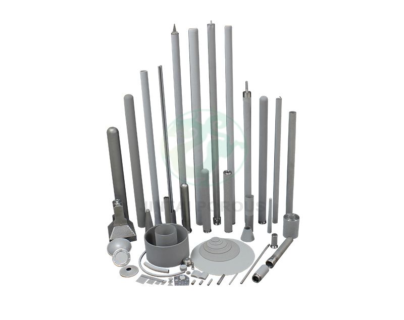
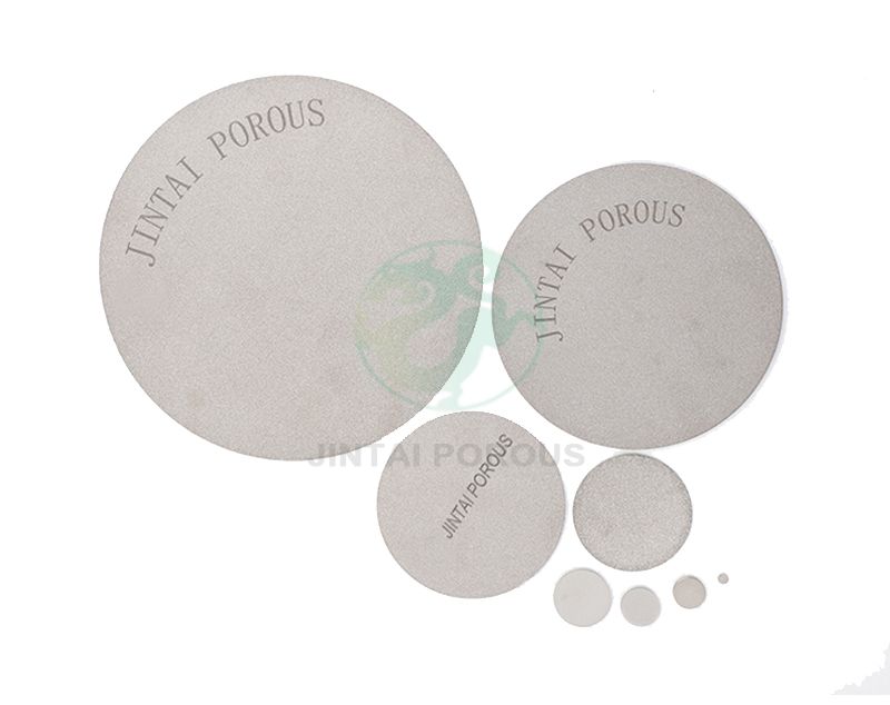
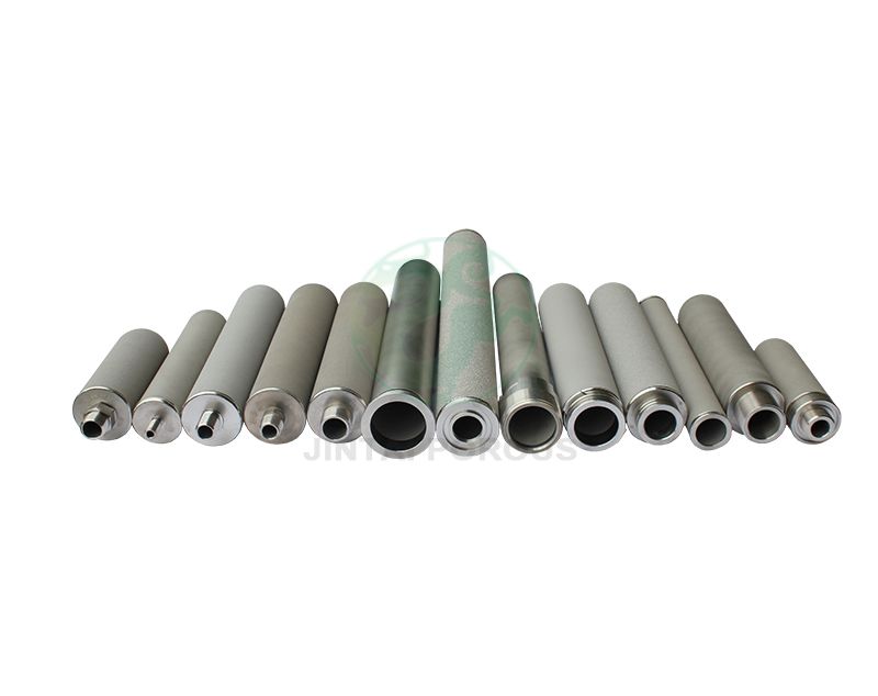
The powder is pressed into the required shape. Tooling can produce tubes, discs, plates, cups, sleeves, and custom inserts. Compaction pressure must be controlled because uneven density can create weak areas or uneven flow.
The compact is heated in a controlled atmosphere. The sintering temperature and holding time depend on the material. The process bonds the particles without closing all the pores. Temperature records are kept for each batch to support traceability.
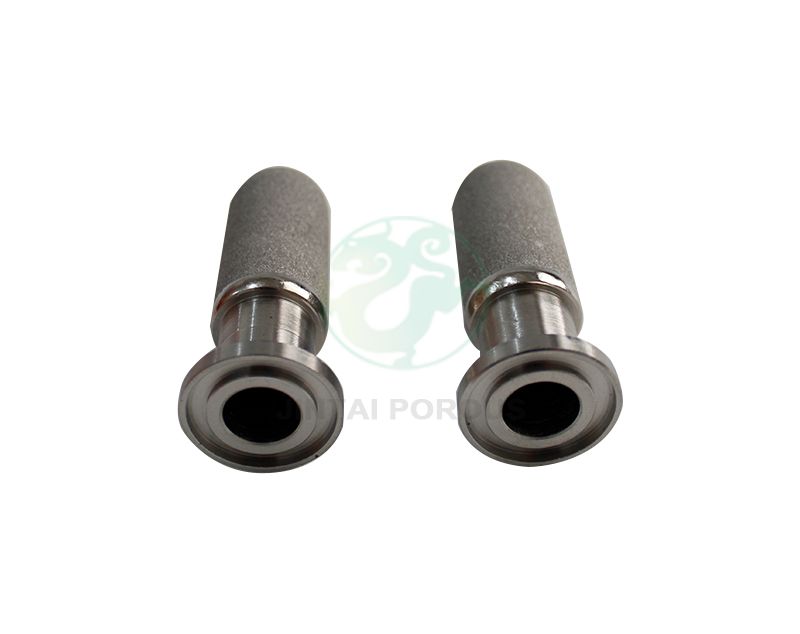
Finishing may include sizing, machining, welding, grinding, electropolishing, or surface treatment. The component is then cleaned to remove loose particles and processing residues. The cleaning process must not block the pores or change the required flow rate.
Each part or production lot is inspected against the drawing and purchase specification. Inspection may include dimensional checks, visual checks, material verification, air permeability, bubble point, pressure resistance, and leak testing.
Calipers, micrometers, height gauges, optical systems, and coordinate measuring machines can verify dimensions. Critical dimensions should be measured with calibrated equipment. Surface defects, cracks, blocked pores, weld defects, and contamination should be recorded.
Bubble point testing helps identify the largest connected pore in a filter. The test uses a wetting liquid and controlled gas pressure. The first continuous stream of bubbles indicates the bubble point pressure. The result can be compared with the approved production value.
Air permeability testing measures the flow rate through a part at a defined pressure difference. Results must state the test gas, temperature, pressure, exposed area, and flow unit. Testing at 20 degrees C may not represent performance at 600 degrees C, so high-temperature correction or application testing may be needed.
Pressure testing confirms that the part can withstand the required operating load. Hydrostatic testing may be used for liquid service. Pneumatic testing requires additional safety controls because compressed gas stores more energy. Helium leak testing may be selected for vacuum and high-purity systems.
Positive material identification can use X-ray fluorescence or optical emission spectroscopy. These methods help confirm alloy chemistry. For clean gas service, particle extraction testing and residue checks may be added. Welding procedures can be qualified under applicable ISO or ASME requirements.
Common references include ISO 2942 for filter element integrity, ISO 4003 for bubble point testing of permeable sintered metal materials, ASTM E384 for microhardness testing, ASTM E112 for grain size evaluation, and ASTM A276 or ASTM A240 for relevant stainless steel product requirements. The correct standard depends on the part type and application. The drawing and quality plan should state the final acceptance criteria.
| Inspection item | Equipment or method | Example control target |
|---|---|---|
| Dimensions | Micrometer, optical system, or CMM | According to drawing tolerance |
| Pore performance | Bubble point and permeability tester | Within approved product specification |
| Material grade | XRF or optical emission spectroscopy | Matches the specified alloy |
| Pressure resistance | Hydrostatic or pneumatic test system | According to design pressure and safety code |
| Surface condition | Visual inspection and microscopy | No cracks, blocked pores, or harmful contamination |
| Cleanliness | Particle extraction and residue inspection | According to process cleanliness requirement |
List the maximum and minimum temperatures. Include start-up, shutdown, and thermal shock conditions. Record the operating pressure, pressure pulses, fluid chemistry, flow rate, and expected particle load. These details are more useful than a general statement such as "high temperature."
Use the smallest pore size that meets the filtration target without creating excessive pressure drop. For gas filtration, consider viscosity changes caused by temperature. For liquid filtration, consider viscosity, solids loading, and cleaning frequency.
A porous part has less solid metal than a dense part. Its strength depends on porosity, shape, wall thickness, alloy, and sintering quality. A thicker wall may improve pressure resistance but reduce flow area. JINTAI can review the balance through sample testing and design verification.
Back-pulse cleaning works well in some gas systems. Ultrasonic or solvent cleaning may be used for smaller components. The cleaning method should be confirmed before production because aggressive chemicals or high pressure can damage welds and pores.
Stainless steel, nickel alloys, and mating components expand at different rates. A tight metal-to-metal fit may create stress during heating. Designers should include suitable clearance, flexible seals, or welded connections where needed.
| Feature | Sintered porous metal | Ceramic | Polymer membrane | Fiberglass media |
|---|---|---|---|---|
| Temperature resistance | High, based on alloy | Very high, but can be brittle | Usually limited by polymer temperature rating | Moderate to high, based on binder and fiber type |
| Impact resistance | Good | Lower than metal in many designs | Moderate | Low to moderate |
| Cleanability | Good with approved methods | Can be cleaned but may crack | Often disposable | Often disposable |
| Custom shapes | Good for tubes, discs, plates, and inserts | Possible but tooling can be complex | Limited by media format | Limited by media format |
| Weldable connection | Available for suitable alloys | Not normally weldable like metal | Not suitable for direct welding | Not suitable for direct welding |
JINTAI supports porous metal component projects from initial design review to regular production. The project process can include prototype samples, material confirmation, pore performance testing, dimensional validation, and production approval. A practical development program may begin with 3 to 10 prototype designs, followed by pilot production and process capability review.
For repeat production, batch records can include powder lot information, pressing conditions, sintering temperature records, machining data, cleaning records, and final inspection results. Sample retention and traceability help identify the cause of any future performance change.
Customers should provide a technical drawing or a basic specification with the following information:
When the final requirement is not known, JINTAI can compare several pore sizes and materials through sample testing. The test results can show the relationship between flow rate, pressure drop, filtration performance, and mechanical strength. This approach reduces the risk of selecting an unsuitable component for full-scale production.
Porous Metal Components for High-Temperature Applications provide a strong solution for filtration, gas distribution, venting, flame control, and pressure equalization. Sintered stainless steel works well for many moderate high-temperature systems. Nickel alloys are better for higher temperatures and more aggressive chemical conditions. The best result comes from matching the alloy, pore size, permeability, wall thickness, and connection design to the real operating conditions.
Reliable production also requires controlled sintering, clean processing, traceable batches, and documented testing. With material review, prototype validation, and inspections such as bubble point, permeability, pressure, and alloy analysis, JINTAI can help deliver porous metal components that perform consistently in demanding high-temperature equipment.