
September 22, 2026

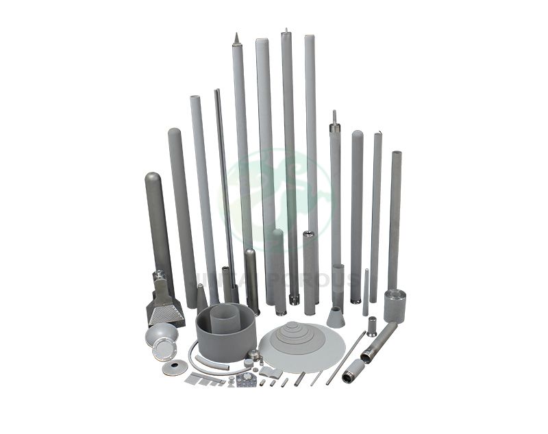
Porous metal components for gas diffusion and distribution help move gas through a controlled network of open pores. In many systems, poor gas flow causes hot spots, low reaction efficiency, unstable pressure, and early component failure. A well-designed gas diffusion layer can spread gas across a surface while limiting pressure drop. The right pore size distribution also supports stable mass transfer in fuel cells, burners, sensors, and industrial reactors. Engineers must balance gas permeability, mechanical strength, filtration efficiency, and corrosion resistance. This balance is one reason companies work with JINTAI to develop custom porous metal parts for demanding gas-handling systems.
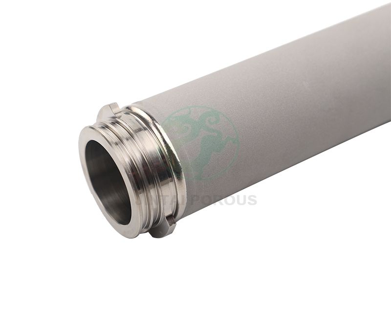
Porous metal components distribute gas by forcing it through connected pores and channels. Sintered stainless steel, nickel, bronze, and other metal powders can form parts with controlled porosity, pore sizes from about 0.5 to 100 micrometers, and porosity commonly between 20 and 45 percent. These parts provide repeatable gas flow, mechanical support, heat resistance, and long service life. The best design depends on gas type, flow rate, operating pressure, temperature, corrosion conditions, pressure drop, and the required level of flow uniformity.
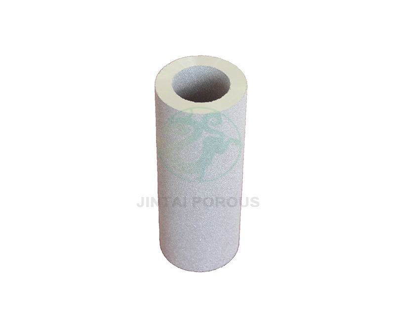
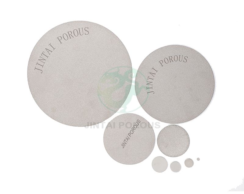
Sintered Porous Metal Components are made by pressing metal powder into a required shape and heating it below the metal's melting point. The heat bonds the powder particles. It also leaves a network of connected pores.
Unlike drilled holes or woven screens, sintered porous metals contain three-dimensional pores throughout the material. This structure allows the component to diffuse, distribute, filter, or restrict gas flow across a large surface area.
Particle size, powder shape, compaction pressure, sintering temperature, holding time, and cooling rate affect the final pore structure. A smaller powder particle can produce smaller pores. Higher compaction pressure usually increases density and reduces open porosity.
Typical design parameters include:
| Parameter | Typical Range or Value | Effect on Gas Performance |
|---|---|---|
| Mean pore size | 0.5 to 100 micrometers | Controls flow resistance and particle retention |
| Open porosity | 20 to 45 percent | Controls the available path for gas flow |
| Thickness | 0.5 to 10 millimeters | Higher thickness can improve distribution but increase pressure drop |
| Flatness | Often controlled within 0.1 to 0.5 millimeters | Supports sealing and uniform contact |
| Surface roughness | Commonly Ra 1.6 to 6.3 micrometers after sintering | Influences sealing, bonding, and gas contact |
Gas diffusion depends on the movement of molecules from a high-concentration area to a low-concentration area. A porous metal part supports this process by creating many small flow paths. These paths increase contact between the gas and the active surface.
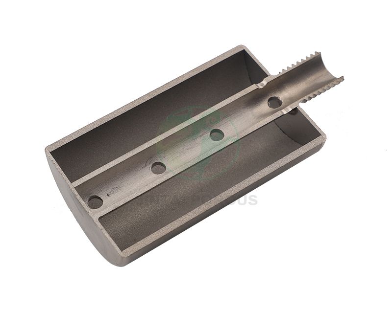
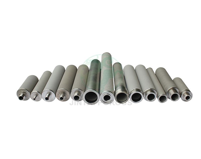
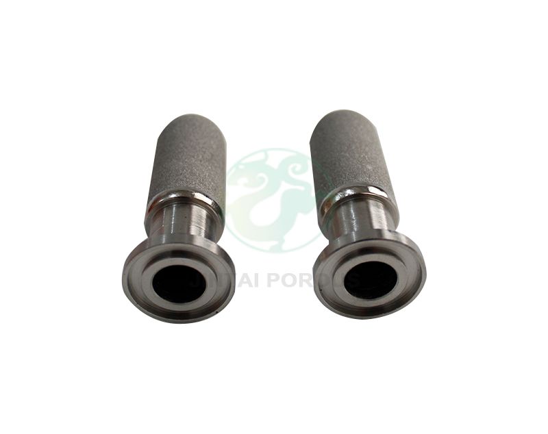
A porous gas distributor can spread gas across a plate, tube, disc, or ring. This helps reduce areas with low flow. It also limits local pressure differences inside the system.
For example, a gas distributor with a 30 micrometer mean pore size may produce a more even flow pattern than a solid plate with a few large holes. The final result depends on thickness, inlet design, gas viscosity, and operating pressure.
Pressure drop is the difference between the inlet and outlet pressure. It is one of the main design factors for porous metal components.
Pressure drop normally increases when:
For many gas diffusion applications, the target pressure drop may range from a few kilopascals to more than 100 kilopascals. The correct value must be confirmed by flow testing under actual operating conditions.
The interconnected pore network increases the available contact area between the gas and the component surface. This can improve mass transfer in gas-liquid contactors, catalytic reactors, electrolyzers, and fuel cell assemblies.
In a fuel cell, the porous material may support a gas diffusion layer, distribute reactant gas, and help remove water. The material must also maintain strength under compression. A typical compressed thickness change should be measured during assembly testing because excessive compression can close the pores.
Porous metal components can distribute hydrogen, oxygen, air, or water vapor. They may serve as a gas diffusion layer support, current-carrying structure, or reactant distributor. Nickel and stainless steel are common choices, but material selection depends on the electrolyte and operating voltage.
Porous metal covers protect sensor elements while allowing gas molecules to pass. The pore size can limit dust and liquid entry. A 5 to 20 micrometer pore range is often considered for fine gas protection, but the exact value depends on sensor response time and contamination risk.
Porous metal burner heads spread fuel gas across the combustion surface. They can support stable flame distribution and reduce local fuel-rich zones. High-temperature alloys may be needed for continuous service above 600 degrees Celsius.
Sintered porous metal filters remove solid particles from compressed air, hydrogen, nitrogen, and process gases. Unlike disposable polymer filters, metal filters can often be cleaned by backflushing, vibration, or controlled thermal treatment.
Porous bronze and stainless steel parts reduce exhaust noise by breaking a fast gas stream into many smaller paths. The part must provide sufficient flow capacity without creating excessive back pressure.
Porous metal tubes and plates can introduce gas into a liquid. The pore size and wetting behavior affect bubble size, contact area, and gas use efficiency.
| Material or Structure | Strength | Temperature Resistance | Flow Control | Cleanability | Typical Use |
|---|---|---|---|---|---|
| Sintered stainless steel | High | High | High when pore size is controlled | Good | Gas diffusion, filtration, sensors, reactors |
| Sintered bronze | Medium | Medium | Medium to high | Good | Pneumatic silencers and low-temperature filters |
| Wire mesh | Medium | High | Limited by mesh openings | Good | Support screens and coarse distribution |
| Perforated plate | High | High | Low unless holes are closely spaced | Very good | Large-flow gas manifolds |
| Polymer membrane | Low to medium | Low to medium | High for selected gases | Limited by chemical compatibility | Gas separation and fine filtration |
| Foam metal | Medium | High | Medium | Medium | Heat exchange and open gas flow |
Sintered porous metal is often selected when a project needs high strength, repeatable pore structure, heat resistance, and the option to weld or braze the component into a larger assembly.
The following process can be used for a custom porous metal gas distributor or filter.
Gas requirements - Material selection - Pore size selection - Geometry design - Prototype production - Flow and strength testing - Design adjustment - Final inspection - Batch production
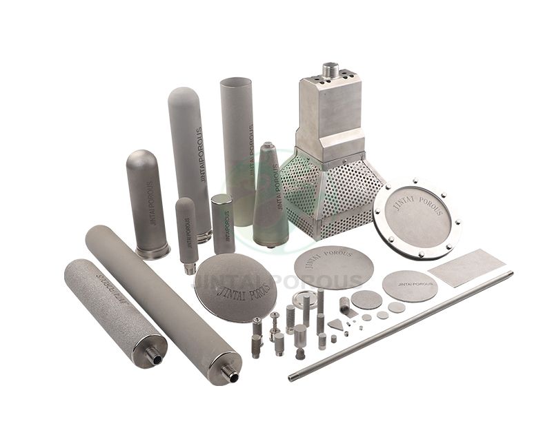
JINTAI can use powder metallurgy, precision forming, controlled sintering, machining, welding, brazing, and surface treatment to produce custom porous metal components. A development project may begin with several pore-size samples. The engineering team can then compare pressure drop and flow uniformity before selecting the production design.
For repeat production, the process should record powder batch, particle size range, compaction pressure, furnace temperature profile, holding time, and final inspection results. These records help reduce variation between production batches.
Testing confirms whether the component can meet its gas diffusion and distribution requirements. The inspection plan should match the application and the risk level of the system.
| Test | What It Measures | Typical Equipment | Useful Result |
|---|---|---|---|
| Air permeability test | Gas flow through the part at a set pressure | Mass flow controller, pressure regulator, differential pressure sensor | Flow rate versus pressure drop curve |
| Bubble point test | Largest effective pore opening or leak path | Liquid wetting system and controlled gas source | Bubble point pressure |
| Pore size test | Mean and maximum pore characteristics | Capillary flow porometer | Pore size distribution |
| Porosity test | Open and total void volume | Density measurement equipment or gas pycnometer | Percentage of open porosity |
| Dimensional inspection | Length, diameter, thickness, flatness, and hole position | Coordinate measuring machine, micrometer, optical projector | Conformance to drawing tolerances |
| Mechanical strength test | Compression, tensile, burst, or vibration resistance | Universal testing machine and pressure test bench | Maximum safe load or pressure |
| Leak test | Unwanted gas leakage around seals or joints | Helium leak detector or pressure decay tester | Leak rate under defined conditions |
Depending on the product type, engineers may use methods related to ASTM F316 for membrane bubble point and pore size measurement, ASTM E128 for air permeability of porous materials, ISO 4003 for air permeability testing of permeable sintered metal materials, and ISO 2942 for filter integrity checks. The selected method should be agreed upon before testing because sample shape, wetting liquid, gas pressure, and reporting format affect the result.
Pore size should not be selected from filtration requirements alone. Gas distribution also depends on flow rate, part area, gas viscosity, and pressure drop.
For a fixed gas and flow area, smaller pores generally increase pressure drop. A thicker part also creates a longer flow path. A larger active area can reduce the gas velocity through the material and lower the pressure drop.
| Design Goal | Possible Design Direction | Main Risk |
|---|---|---|
| High gas flow | Larger pores, higher open area, lower thickness | Lower particle retention and weaker distribution control |
| Fine particle retention | Smaller pores and greater thickness | Higher pressure drop and faster blockage |
| Uniform surface flow | Controlled pore distribution and suitable manifold design | Higher manufacturing cost |
| High mechanical strength | Higher density and greater thickness | Lower permeability |
| High-temperature service | Nickel or stainless steel alloy with suitable sintering conditions | Oxidation or thermal distortion if the atmosphere is unsuitable |
For a long-tail application such as a custom sintered stainless steel gas diffuser for hydrogen systems, the design must also consider hydrogen embrittlement, sealing, surface oxidation, and pressure cycling. These factors may require testing with the actual gas instead of air.
Providing these details early can reduce prototype changes. It also helps the manufacturer select a suitable powder, forming method, and furnace cycle.
Porous metal components for gas diffusion and distribution provide a controlled path for gas flow. Their connected pore network supports uniform distribution, mass transfer, filtration, and pressure control. Sintered stainless steel, nickel, bronze, titanium, and other alloys can be designed for different temperatures, gases, pore sizes, and mechanical loads. A reliable result requires more than choosing a material. It requires testing the pore size distribution, permeability, pressure drop, strength, dimensions, and leak performance. With controlled manufacturing and inspection, JINTAI can help develop porous metal components that match the gas system's operating requirements.